one year ago
Hi everyone,
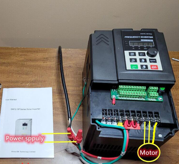
I'm working on wiring up a 3 hp VFD that takes 120V single-phase input and outputs 230V three-phase to run a 230V three-phase AC motor. VFD Model: GK3000-SP1S1-2d2
When I received the VFD, it already had some wires connected: a green wire labeled "N" and a red wire labeled "L." I’ve attached some pictures to give a better idea of what’s going on.
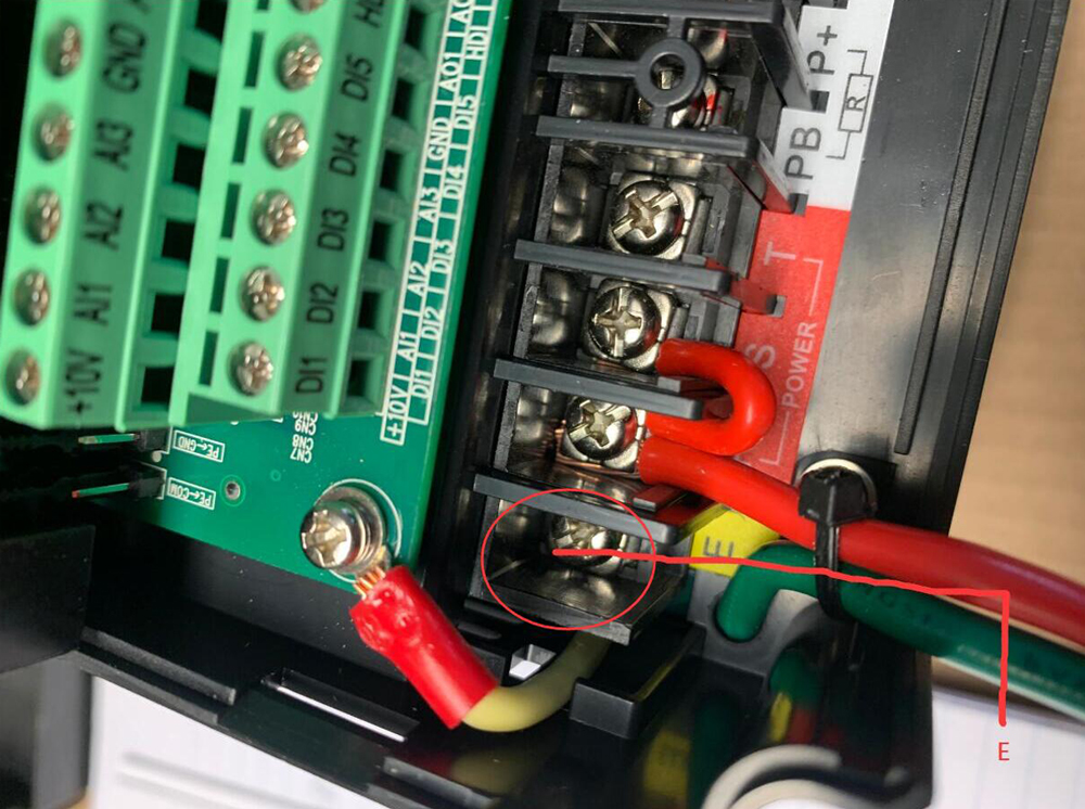
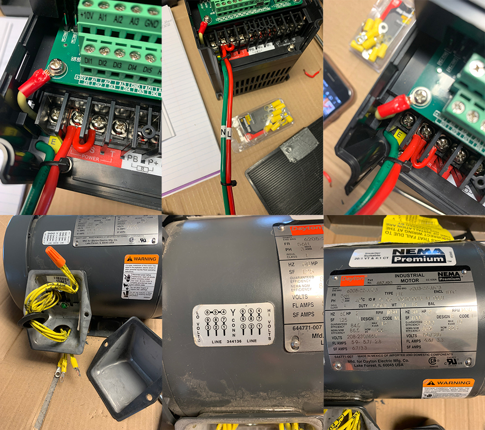
I'm very new to electrical wiring, so I'm a bit confused about a few things. Typically green wires are the ground wires, and the green wire in this case goes inside the VFD itself, so I'm not sure where it's attached to. On the external wiring part, there's a screw labeled "E" which in the manual is the ground. Is this green wire the ground wire, just grounded internally? So I wouldn't need to attach a wire to the external "E" screw to ground it?
The VFD also came with 1 red wire, which was attached to the "R" screw. There was then another small red wire that ran from the "R" screw to the "S" screw", then another red wire from "S" to "T". I understand this to be the input power to the VFD, and the U, V, and W screws are the 3-phase 230v output that'' connect to the motor. Most videos I've watched show a red wire and a black wire connected to the R and S screws for 120v 1-phase input. But in the case of the VFD wiring the way it came it's the red wire attached to the R, S, and T screws. I just wanted to make sure that there wasn't another wire necessary, and to clarify which of the R, S, and T screws the wires should be attached to for 1-phase 120v input.
We planned to plug it into a wall outlet using just a typical 2-prong male connector. Is that how we should plug it in as well?
I’d really appreciate any help or advice! Let me know if any more details or photos would help.
Thanks in advance!
I'm working on wiring up a 3 hp VFD that takes 120V single-phase input and outputs 230V three-phase to run a 230V three-phase AC motor. VFD Model: GK3000-SP1S1-2d2
When I received the VFD, it already had some wires connected: a green wire labeled "N" and a red wire labeled "L." I’ve attached some pictures to give a better idea of what’s going on.
I'm very new to electrical wiring, so I'm a bit confused about a few things. Typically green wires are the ground wires, and the green wire in this case goes inside the VFD itself, so I'm not sure where it's attached to. On the external wiring part, there's a screw labeled "E" which in the manual is the ground. Is this green wire the ground wire, just grounded internally? So I wouldn't need to attach a wire to the external "E" screw to ground it?
The VFD also came with 1 red wire, which was attached to the "R" screw. There was then another small red wire that ran from the "R" screw to the "S" screw", then another red wire from "S" to "T". I understand this to be the input power to the VFD, and the U, V, and W screws are the 3-phase 230v output that'' connect to the motor. Most videos I've watched show a red wire and a black wire connected to the R and S screws for 120v 1-phase input. But in the case of the VFD wiring the way it came it's the red wire attached to the R, S, and T screws. I just wanted to make sure that there wasn't another wire necessary, and to clarify which of the R, S, and T screws the wires should be attached to for 1-phase 120v input.
We planned to plug it into a wall outlet using just a typical 2-prong male connector. Is that how we should plug it in as well?
I’d really appreciate any help or advice! Let me know if any more details or photos would help.
Thanks in advance!
0