8 months ago
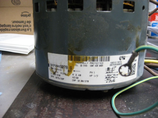
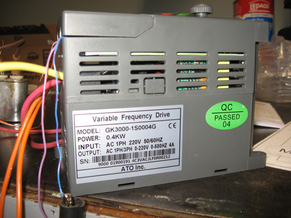
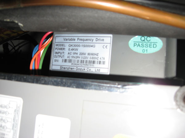
Hi, I am having problems with the replacement of a bad 1/2 hp single phase VFD with a new one (SKU: GK3000-1S0004) of the same type. The new one received is not working: the motor is not running, and always receiving E12 error on the LED display. It seems that the new parameters are different from the old one. The app implies a 230 VAC fan motor (1/3 HP) working at 2 different speeds based on 45Hz to 75Hz received from the VFD and controlled by x1-com contacts.(default 45HZ)
I am using the new parameters different for factory one:
P0.01 =1
P0.02 = 45Hz
P0.03= 1
P0.05=75Hz
P0.06=75hz
P0.07=45Hz
P3.00=1
I have checked: input voltage is ok, (L1-L2) all connections are ok, motor is ok in regular AC input, X1-COM ok.
What is the problem? Thank you!
I am using the new parameters different for factory one:
P0.01 =1
P0.02 = 45Hz
P0.03= 1
P0.05=75Hz
P0.06=75hz
P0.07=45Hz
P3.00=1
I have checked: input voltage is ok, (L1-L2) all connections are ok, motor is ok in regular AC input, X1-COM ok.
What is the problem? Thank you!
0