7 months ago
Hi everyone,
I recently purchased six ATO current transmitters (24 VDC supply, 0–20 mA output). Before we put them into service, I’d like to sanity-check our understanding of the wiring and hear from anyone who has used these units before.
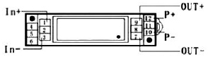
Based on the wiring diagram in the ATO catalog, this is how we’re currently interpreting the terminals:
P+: +24 VDC operating power
P−: 0 V return for the 24 VDC supply
In+: Positive side of the measured signal (in our case ~15 VDC, corresponding to about 3.5–16 mA)
In−: Return / 0 V of the measured signal source
If any of the above looks wrong, please feel free to point it out.
Where things get a bit unclear for us is the output wiring:
Out+: Presumably the 0–20 mA signal going to the PLC analog input (the PLC input is a sinking type)
Out−: This is the confusing part — should this be tied to +24 VDC to power the loop, or is it simply a 0 V reference/common?
For context, we’re already using two other instruments in the same system:
A 2-wire, loop-powered pressure sensor, where OUT− is tied to +24 VDC, OUT+ carries the 0–20 mA to the PLC, and the loop is completed through the PLC common. A self-powered level sensor, where OUT+ provides the 0–20 mA signal and OUT− connects directly to the PLC 0 V common. Both ultimately feed sinking PLC analog inputs, but one requires +24 V on the output loop and the other requires 0 V.
So the key question is: Which of these wiring methods applies to the ATO current transmitter?
Is it behaving like a loop-powered output, or a self-powered (active) 0–20 mA source?
Any insight or real-world experience would be greatly appreciated.
I recently purchased six ATO current transmitters (24 VDC supply, 0–20 mA output). Before we put them into service, I’d like to sanity-check our understanding of the wiring and hear from anyone who has used these units before.
Based on the wiring diagram in the ATO catalog, this is how we’re currently interpreting the terminals:
P+: +24 VDC operating power
P−: 0 V return for the 24 VDC supply
In+: Positive side of the measured signal (in our case ~15 VDC, corresponding to about 3.5–16 mA)
In−: Return / 0 V of the measured signal source
If any of the above looks wrong, please feel free to point it out.
Where things get a bit unclear for us is the output wiring:
Out+: Presumably the 0–20 mA signal going to the PLC analog input (the PLC input is a sinking type)
Out−: This is the confusing part — should this be tied to +24 VDC to power the loop, or is it simply a 0 V reference/common?
For context, we’re already using two other instruments in the same system:
A 2-wire, loop-powered pressure sensor, where OUT− is tied to +24 VDC, OUT+ carries the 0–20 mA to the PLC, and the loop is completed through the PLC common. A self-powered level sensor, where OUT+ provides the 0–20 mA signal and OUT− connects directly to the PLC 0 V common. Both ultimately feed sinking PLC analog inputs, but one requires +24 V on the output loop and the other requires 0 V.
So the key question is: Which of these wiring methods applies to the ATO current transmitter?
Is it behaving like a loop-powered output, or a self-powered (active) 0–20 mA source?
Any insight or real-world experience would be greatly appreciated.
0
