one year ago
Hello! I would like to use one of a single phase to single phase VFD drives for my lathe motor.
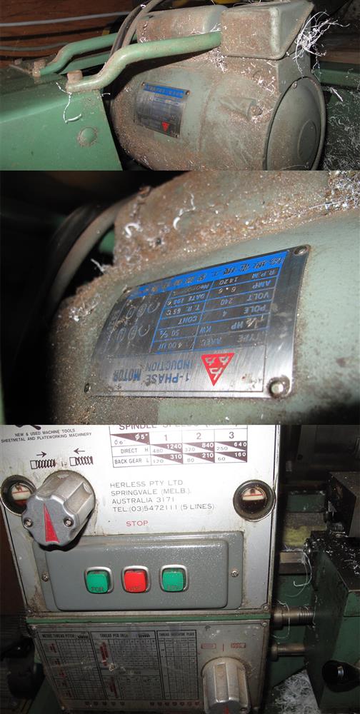
My lathe motor is 1.5 HP (1.1 kW) single phase. From the photos, it appears to have a single 400 uF capacitor. It does have a centrifugal switch because I can hear this operate. There are 3 wires (plus earth wire) from the reversing switch to the motor.
Most of the time the lathe is used for winding small coils of wire, which requires very little torque from the motor. Occasionally I use it as a metal cutting lathe, but again, I do not work the motor hard. High starting torque is not required, just enough to get the lathe chuck spinning.
The reason I want electronic speed control is for coil winding. As standard, the maximum chuck speed is only 1200 RPM, which is too slow for winding coils with many thousands of turns of fine wire. I would like to be able to run the motor up to twice the rated speed of 1440 RPM, but the torque requirement is very low.
Is there a 1.5 kW single-phase to single-phase VFD units suitable? By what factor would I be able to increase motor RPM above standard, under essentially no load? Is there a circuit for how I would electrically connect this motor? Would this motor have to start windings that are operated by the centrifugal switch? If so, would the starting winding be used with this VFD unit?
0
