Solid State Relays
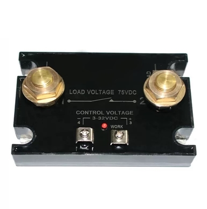
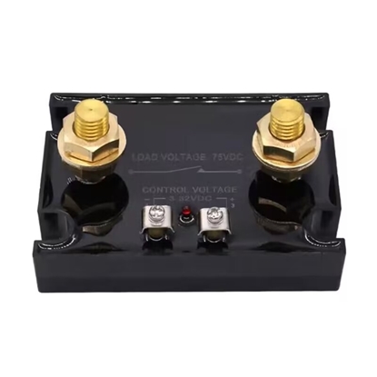
500A SSR Solid State Relay, 3-32V DC to DC
Solid state relay SSR-15AA, 15A 90-280V AC to AC
Solid state relay SSR-15DA, 15A 3-32V DC to AC
1000A SSR Solid State Relay, 3-32V DC to DC
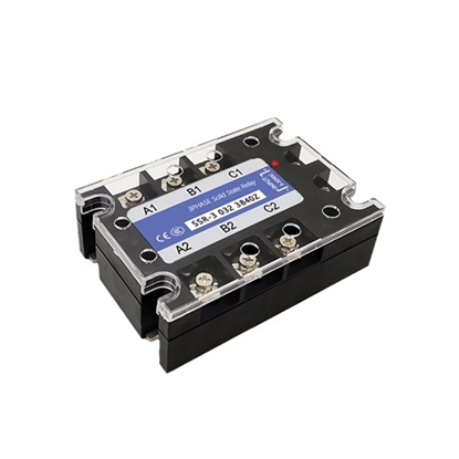
Solid State Relay, 3-phase, 150A/200A, DC to AC SSR
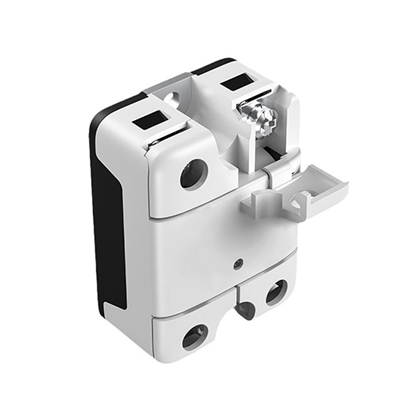
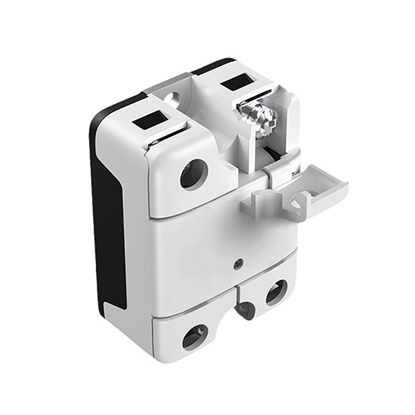
A solid state relay (SSR) is a non-contact switch composed of microelectronic circuits, discrete electronic devices, electronic power devices, realizing the isolation between the control side and load side. A solid state relay is applied to control high current load with inputting a small control signal. Compared with the electromagnetic relay (EMR), the solid state relay is more reliable, non-contact, long life, high speed and little interference, and it has been widely used.
ATO provides single phase and three phase solid state relays, including DC-AC and AC-AC, with load current from 10A to 120A. In addition, compact-size industrial solid state relays are provided with DC control AC, load current ranging 60 amp, 80 amp, to 350 amp. More details are as below and you can select a most suitable one to switch on/off your facilities or machines.
What are the Features of Solid State Relay?
- SSRs have no internal mechanical elements and full-sealed perfusion in the structure. Therefore, SSRs have advantages such as vibration resistance, corrosion resistance, long life and high reliability.
- Low noises. AC SSRs use zero-crossing triggering technology, thus effectively reducing the voltage rise rate dv/dt and current rise rate di/dt on the line, making SSR minimal interference to the power supply in the long-term working.
- Switching time is short, so SSRs can be used in high frequency applications.
- Optoelectronic isolation is used between input circuits and outputs circuits, and insulation voltage is more than 2500V.
- Low input power consumption, compatible with TTL and COMS circuits.
- Protection circuit is set in the output terminals.
- High load capacity.
Differences between Solid State Relays (SSR) and Electromagnetic Relays (EMR)
| Items | Electromagnetic relay (EMR) | Solid state relay (SSR) |
| Structure | A magnetic switch made up of relay coils, movable elements, contact system etc., mechanical motion inside | An electronic switching device composed of thyristor, SCR, high-power transistor etc., no mechanical motion components inside, optically isolated between input and output |
| Working method | Control on-off state of circuits through electromagnet force based on the electromagnetic induction principle | Achieve isolation and relay switching on/off functions relying on electric, magnetic and optical characteristics of semiconductor devices and electronic components |
| Working status | Slow response, some noises, limited lifetime | Quick response, no noise, long lifespan |
| Operating environment | Not as good as SSR | Suitable for corrosion, moisture, dust, high altitude, electromagnetic interference and other harsh environments |
| Electrical performances | Simple drive, good isolation, good short-term overload tolerance, but large power consumption | No electric spark, no contact, fast switching speed with a small control signal to control high-current load |
How to Wire Solid State Relay?
Use a 40A solid state relay with 3~32V DC control voltage and 24~480V AC Load voltage. The protective cover is removed to reveal four terminals. 3 and 4 are control terminals, 1 and 2 are output terminals, and a red indicator light. After wiring is completed, press the button to connect the solid state relay, the indicator light is on, and the solid state relay runs normally.
If the switching current of relay exceeds 10A, relay heating will increase. Therefore, heat conduction grease can be coated on the back of the solid state relay, and then heat dissipation can be added. You can watch the video below to learn more about solid state relay wiring.
What Causes a Solid State Relay Burnout?
- Selection of SSR rated current
This is probably because the rated loading capability of the solid state relay you selected is lower than the practical loading power. In addition, the surge current of the load may also damage the solid state relay if it exceeds the overloading capability of SSR.
For the above issue, the solid state relay should be selected properly based on the different types of loads. For the resistive load, the actual load current is not recommended to be higher than two-thirds rated current of the solid state relay. For the inductive load, the load current should be no higher than one-half rated current of SSR. It is required to equip the SSR with the overload protective device. When selecting a solid state relay, the SSR with higher rated current should be selected if possible, so as to guarantee the enough current margin. - SSR DC or AC type
Please note that solid state relay is divided into DC mode and AC mode. DC SSR is only used to control DC power and DC load while AC SSR is just for controling AC power and AC load. When selecting a solid state relay, please pay attention if it is selected correctly based on the working condiitons. - Installation environment
The ambient temperature also really matters. So, the heat radiator should be equipped with if the load current is higher than or equivalent to 10A. Besides, it is also recommended to connect a varistor in series at output side as an over-current protection measure.
Filter by:
Clear All
