6 months ago
Hi all! It's been about 6 months since we ordered these VFDs, but we're only now finishing the wiring and final assembly.
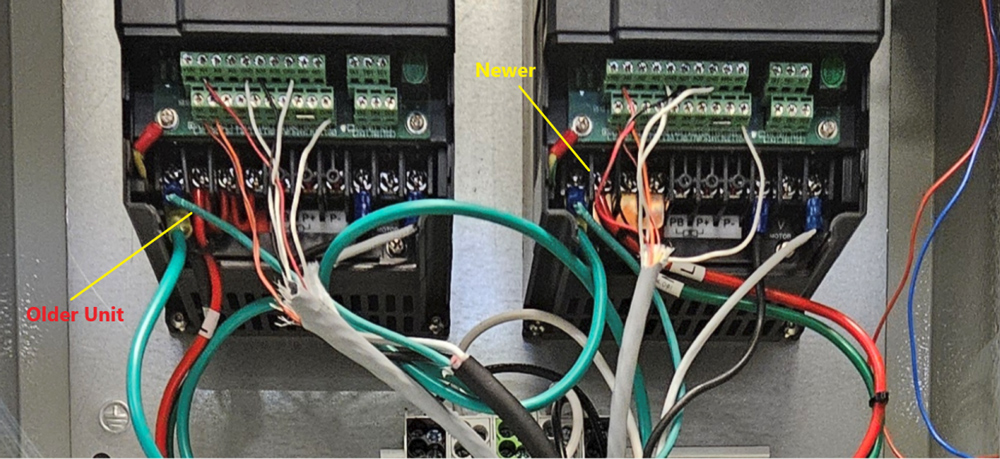
We ordered two VFDs in total. The first one was ordered on August 31, 2023. The second unit was ordered by me last July. The older VFD (on the left) powers up and works fine. It has red jumper wires on the primary power input bus bar.
The second VFD (on the right) uses a solid copper bus bar, and it has never powered up. We've verified that 120V AC input power is present on both units (marked in red in the photo). My question: Are there any known issues or differences with the copper-bus-bar version that could explain why it won't power up?
0
