Servo Drives

AC Servo Drive for 200W-400W Servo Motor

AC Servo Drive for 400W-1000W Servo Motor

AC Servo Drive for 1kW-2.6kW Servo Motor

AC Servo Drive for 2kW-5.5kW Servo Motor

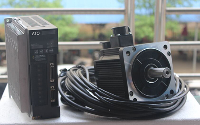
AC Servo Drive for ATO Servo Motor
Servo Drive, also known as servo amplifier, is a controller used to control servo motors, which is part of the servo system and is mainly used in high-precision positioning systems. Generally, the servo motor is controlled by position, speed and torque.
Cheap and high-quality 220V and 380V AC single-phase/three-phase servo drives for sale online. ATO servo drives are perfectly matched with brushless AC servo motors from 50W to 7.5kW, providing control modes of position control and speed control.
Servo drive working principle
The servo driver adopts a digital signal processor (DSP) as the control core and realizes the complex control algorithm, digitization, networking, and intelligentialization. The power device of servo amplifier generally adopts an intelligent power module (IPM) as the driving circuit of the core design. IPM integrated drive circuit with over-voltage and over-current, overheating, under-voltage fault detection and protection circuit. The soft-start circuit is also added in the major loop, so as to reduce the impact on the drive in the start-up process.
The power drive unit is rectified by the three-phase full-bridge rectifier circuit to input the three-phase electric or municipal power, and the corresponding DC power is obtained. The three-phase power or electric supply after rectifying can drive the AC servo motor through three-phase sine PWM voltage source inverter frequency conversion. The whole process of the power drive unit can be simply described as the process of AC-DC-AC. The main topology of the rectifier unit (AC-DC) is the three-phase full-bridge uncontrolled rectifier circuit.
3 methods for servo control system
Servo drive generally has three control methods: position control mode, torque control mode and speed control method.
- Position control mode can determine the rotational speed generally through the external input pulse frequency and the rotation angle by the number of pulses. Some servo systems can assign velocity and displacement directly by means of communication. Because the position mode can control the speed and position strictly, it is generally used in the positioning device.
- Torque control mode is assigned by the external analog input or direct address to set the external output torque of the motor shaft. The torque can be changed by changing the setting of the analog immediately and the corresponding address value can be realized by the change of communication mode. The main application has strict requirements for the material on stress in the winding and unwinding device, such as winding device or fiber optic equipment. The setting of the torque should be changed at any time according to the radius of the winding so as to ensure that the force of the material does not change with the change of the winding radius.
- Speed mode can have to control the rotation speed through the input of the analog quantity or the pulse frequency. The outer loop PID with the upper control device can be positioned. But the position signal of the motor or the position signal of the direct load should be sent to the upper feedback for calculation. The position mode also supports a direct load loop detection position signal. At this moment, the coder at the motor shaft end can only detect the motor speed and the position signal is provided by the detection device directly at the final load end. The advantage of this method is that it can reduce the error in the intermediate transmission process and increase the positioning accuracy in the whole system.
Servo Motor Driver vs. Stepper Motor Driver
Different working principle
A stepper motor driver is an electronic product that emits a uniform pulse signal. The signal it emits enters the stepper motor driver and is converted by the driver into a strong current signal required by the stepper motor to drive the stepper motor to run. A servo driver is a controller used to control a servo motor. Its function is similar to that of a frequency converter that acts on an ordinary AC motor. The servo motor driver is a part of the servo system and is mainly used for high-precision positioning systems. In general, servo motors are controlled by three methods: position, speed and torque.
Different circuit composition
- Circuit composition of a stepper motor driver: Motor drive circuit. The stepper motor drive circuit is designed on the basis of an H-bridge circuit. The construction of a dual H-bridge drive circuit using discrete components MOS tubes is a proven motor control scheme. The circuit is not complicated. Depending on the operating current of the MOS tubes, the upper limit of the current can even reach several tens of amperes. It is an ideal solution for stepper motor drive.
- Circuit composition of the servo motor driver: Motor rectifier circuit. The main topology circuit of the rectifier unit is a three-phase full-bridge uncontrolled rectifier circuit, which is essentially a series of three-phase half-wave controlled rectifier circuits with a set of common cathodes and a set of common anodes. It is customary to connect the cathodes together.
