Control Circuit for Solid State Relay
Solid state relays (SSRs) have plenty of types and models, so its input control methods and control circuits are numerous accordingly. The common characteristics of solid state relay (SSR) lie in the small drive current or drive voltage, namely, the on-off the SSR can be controlled by just inputting a small signal.
If it is required to realize effective and reliable control, its input signal should reach a given value. As to the requirement to the working current of the input loop, it is recommended to switch on when the value is 5-10mA and switch off when the value is lower than 1mA. As to the requirement of the working voltage of the input terminal, it is generally no lower than 3V in switch on, and lower than 1V in switch off. Of course, because of the different product characteristics and different manufacturers, the requirement to the input current or resistance value is also different. Therefore, in using and designing the circuit, the selection and design can be conducted according to the specification and operation occasions on the basis of solid state relay (SSR) type. The following text introduces some basic methods and circuits of SSR input control.
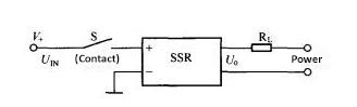
1. Contacts control a SSR
A group of mechanical contacts are used to control the circuit of SSR directly. As shown in the circuit diagram below, S in the diagram can be a mechanical switch, a relay or an electronic switching circuit.
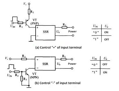
2. Transistor control on-off of a SSR
Solid state relay (SSR) can be controlled directly by NPN type or PNP type transistor (As shown in circuit diagrams a and b below). In the Diagram a, VT is open at ordinary time, and SSR is in on-state. When there is an impulse, SSR is disconnected. As shown in Diagram b, VT is closed and SSR is in off-state at ordinary time. When there is an impulse, SSR is connected.
As to the common solid state relay, the minimum input working voltage is required to be 3V (on-state). If it is lower than 1V, solid state relay will be switched off.
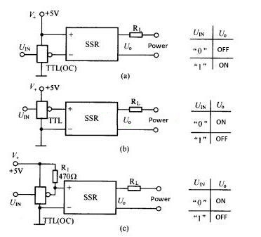
3. Control a SSR via TTL digital integrated circuit
As shown in the control circuit diagrams below, it adopts TTL digital integrated circuit to drive the solid state relay and control the on-off of the SSR.
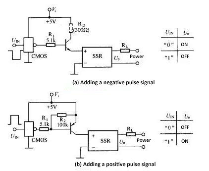
4. Control a SSR via CMOS digital integrated circuit
The input impedance of CMOS device is high, and the output logic level has great swing amplitude (high-low level value is approaching to power source voltage). It is very suitable to coordinate with SSR and other circuits. For the static and dynamic power consumption of CMOS device, the static power consumption is about 10nW while the dynamic power consumption is several mW. In order to ensure the operation safety of CMOS device, the circuit adopts transistor to buffer and isolate (as shown in the circuit diagram below).
5. Control a SSR via impulse signal
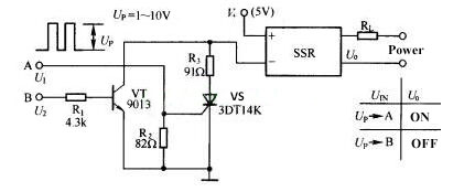
The drive circuit is connected with the “-” input terminal of solid state relay. Adding the impulse signal with the amplitude of Up on the A terminal can trigger silicon controlled VS to open, so as to make the SSR connected. The status will being maintained even after the impulse discharges. If the terminal B is exerted with another positive impulse signal at this time, VT will be connected, and its collector is at a low level. After VS is switched off and the impulse discharges, SSR turns to be off-state.
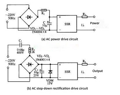
6. Control a SSR by AC power