Current Transformer Working Principle
Working principle of the current transformer is based on the electromagnetic induction principle, circuit current often flows through its primary winding. When the current transformer works, its secondary circuit keeps closed, therefore, the impedance of series coil of measuring instrument and protection circuit are very small, the working state is close to the short circuit.
Current transformer consists of closed iron core and winding. It has few primary winding that are connected in series in the current circuit under measurement; however, it has many secondary winding, which are connected in series in the measuring instrument and protection circuits. The current transformer plays the role of converter and electrical isolation, it's a sensor for measuring instrument, relay protection and other secondary equipment to obtain current information of primary circuit in power system. It converts the high current to a low current by ratio, its primary end is connected with the primary system, while the secondary end is connected with the measuring instrument and relay protection.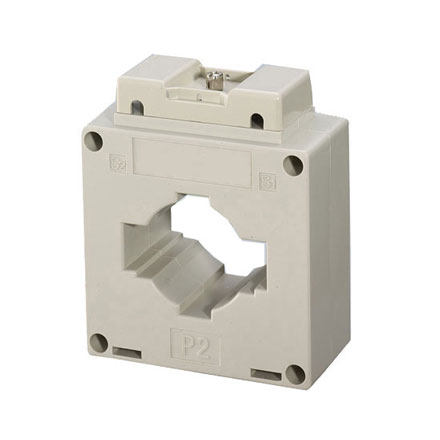
In the ideal current transformer, if we assumed the no-load current Ⅰ0=0, then total magnetic potential Ⅰ0N0=0. Based on the energy conservation law, magnetomotive force of the primary winding is equal to that of secondary winding, namely I 1NI= -I 2N2.
Namely, the current of current transformer is inversely proportional to its turns. The ratio between the primary current and the secondary current, I1/I2, is called the current ratio of current transformer. If the secondary current is given, the primary current can be obtained, the phasor difference between the secondary current and primary current is 1800.
The current transformer consists of primary coil, secondary coil, iron core, insulation support and outlet terminal. The iron core is made of silicon steel sheets, the primary coil is connected in series with the main circuit. Through the measured current I1, the primary coil produces alternating magnetic flux in the iron core, which promotes the secondary coil to induce corresponding secondary current I2. If excitation loss is neglected, I1n1=I2n2, among, n1 and n2 refer to the turn number of primary coil and secondary coil respectively. Transformer ratio of the current transformer is K=I1/I2=n2/n1.
As the primary coil is connected in the main circuit, proper insulation material should be adopted for the grounding of primary coil, so as to ensure the safety of secondary circuit and personal safety. The secondary circuit consists of secondary coils, meters and current coils of the current transformer, the current transformer can be divided into two types, namely the measuring current transformer and protective current transformer.
Buying low cost current transformers on ATO.com now, various current ratios are available for your choice 10/5A, 200/5A, and 600/5A......

Want information about 2 runs of cable entry in single CT. How it works ?