How do you Calibrate a Digital Inclinometer?
A digital inclinometer is an instrument used to measure angles. It is used in a wide range of applications, such as in machinery manufacturing, aerospace, precision measurement, construction and photography, and so on, where angle measuring instruments can be applied. In order to better use the digital display inclinometer to measure accurate values, it is very necessary to calibrate the inclinometer. Next, we will introduce several common calibration methods. Interested friends will learn together.
Combination of sine gauge and gauge block (method 1)
Regular is a measuring instrument that uses the principle of sine to generate angles with the help of gauge blocks. Place the sine gauge on the flat plate, place the measured digital inclinometer on the gauge, and adjust the digital inclinometer to zero. According to the formula sinθ= d / l, (d is the size of the gauge block, the distance between the centers of the cylinders on both sides of the sine gauge), calculate the size of the gauge block required for the angle to be calibrated. Place 5 equivalent blocks of the size required for the calibration point of the corresponding instrument under the cylinder of the sine gauge in turn, so that the sine gauge and the plate form a corresponding angle, and read the displayed values of the digital display inclinometer one by one.
The advantage of this instrument calibration method is that the standard instruments used are sine gauges and equal blocks that are available in general metrology institutions, which is convenient for the measurement to be carried out. The disadvantage is that when using this method, it is necessary to calculate the gauge block of the size corresponding to the calibration angle. However, the size of the gauge block is limited. When calibrating a specific angle value, it may not be possible to configure and combine gauge blocks of the corresponding size, resulting in the inability to calibrate any angle, which has certain limitations.
Optical dividing head (method 2)
The optical dividing head is a goniometric instrument with the optical dial, circular grating, or circular induction synchronizer as the graduation element, and can measure within its circumference or any angle. When calibrating the digital inclinometer, attach the digital inclinometer to the attachment of the central axis of the optical graduation head horizontally, and then place the optical graduation head at a certain full graduation line, and the display value of the inclinometer returns to zero. According to calibrate angle rotate the optical dividing head, and the inclinometer will also rotate with it.
The difference between the indication value of the inclinometer and the rotation angle of the optical dividing head is the indication error of this point. The advantage of this measurement method is that it can be calibrated at any angle, has high accuracy, strong intuitiveness, does not require too much calculation, and is easy to operate. However, the cost of the optical dividing head instrument is relatively high, there are two alignment errors in the detection process, and there are relatively many errors introduced by human factors.
How to test the digital display inclinometer?
Small drift
After the instrument is preheated and stabilized, place the instrument on the plate, read the indication value of the instrument at intervals of 1 h within 2 consecutive hours, and take the maximum value of the difference between all indication values and the initial indication value as the drift of the instrument.
Indication error
Place the sine gauge, gauge block, and standard square on the flat plate that has been adjusted to a level, then place gauge blocks of the size required for the corresponding calibration position under the cylinder of the sine gauge in turn, and read them one by one on the instrument. The instrument measures in the forward and reverse directions of 15°, 30°, 50°, 60°, and 90°. The difference between the indicated value of the instrument and the standard angle value produced by the corresponding sine gauge is the indication error of the instrument at each calibration position. Then turn the sine gauge together with the instrument by 180°, use the same method to calibrate the negative angle of the instrument, and take the indication error corresponding to the maximum value of the absolute value of each calibration position error as the indication error of the instrument.
Recalibration interval
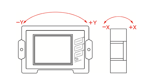
According to the actual use of the instrument, the recalibration interval can be determined by the user, and it is generally recommended that the  recalibration interval be 1 year. First put the digital inclinometer into the inclinometer tube, so that the guide wheel completely enters the guide groove. The direction should be the positive direction of the guide wheel, and the measured value is positive when it is consistent with the positive direction of the measured displacement coordinate (+X), and the opposite is negative.
Then measure the inclination angle of the axis of the inclinometer relative to the reference axis for each basic length according to the mark marked on the cable. The test method should follow the following two points: When the lower part of the inclinometer tube is reliably fixed in the bedrock (the buried depth should be greater than 5000mm), it can be determined that the bedrock has no displacement. At this time, the measurement can be measured from bottom to top until the nozzle. When the bottom of the inclinometer pipe is suspended (the bottom is not fixed to the bedrock), the measurement should be carried out from top to bottom.
Monitoring data collection and analysis
The collection, arrangement, and analysis of monitoring data generally adopt an automated integrated processing system. This automatic data acquisition and processing system can double the work efficiency and quality. It is a computer program based on the parameters of the inclinometer and related calculation formulas, and the results are output in the form of tables and graphics.
Error reduction measures
In order to improve the measurement accuracy, during the measurement, when the four guide wheels do not fully enter the guide groove in a certain measurement section, the arithmetic sum value S will change greatly. Therefore, when measuring, the four guide wheels must be fully inserted into the guide groove, and the joints of the measuring tubes can be measured several times. If the sum value of one or two places deviates significantly from the normal value, it can be eliminated. This is all caused by the fact that one end of the guide wheel is not in the guide groove, and this situation often occurs at the pipe joint.
In order to eliminate the systematic error, the displacement (inclination angle) of each direction (±X, ±Y) should be measured and read in the forward and reverse directions one by one, and half of the difference is used to calculate the displacement of each segment. That is: F= [(+X, +Y)-(-X,-Y)]/2, F is the real-time electrical measurement value of the inclinometer, the unit is mv; ± X, ± Y are the test readings in each direction, the unit is mv.
Since the calculated value of half of the sum of the two measured values in the forward and reverse directions on the same section of the entire inclinometer should be the reading value of the inclinometer in the theoretical vertical state, this F should be a fixed value. If the measured value F is discrete, it may be caused by the following four situations:
- The geometric connection lines of the front and rear sets of guide wheels of the inclinometer are not completely parallel in the forward and reverse measurements.
- The cooperation between the guide wheel and the guide groove is not good.
- The gap between the guide wheel and the wheel frame is too large.
- The inclinometer tube and bentonite ball are not good.
Arranging observation points and forming holes
For a site or structure, observation points should be arranged reasonably according to local conditions. Generally, the horizontal distance between adjacent observation points is required to be one borehole depth, and the observation points can also be appropriately densified or reduced according to the grade of geotechnical engineering. During construction, it is required that the drilling is plumbed as much as possible. The diameter of the hole should be 30mm larger than the outer diameter of the inclinometer pipe, and the drilling depth should exceed the deepest displacement zone by 5m. All boreholes should be inspected and accepted before embedding the inclinometer pipe, and can only be buried after passing the test.
Assembly of the inclinometer
The inclinometer must be inspected and calibrated before the test, and the preparations before the test must be done before assembly.
Installation of the inclinometer tube
The installation quality of the inclinometer tube is the key to the test effect, and the following steps should be followed:
- Install the inclinometer tube on the bottom cover of the tube and fix it with screws or glue.
- Put the inclinometer tubes into the borehole one by one in sequence, connect the inclinometer tubes with connecting pipes, and fix them with screws. During the installation of the inclinometer pipe, attention should be paid to the direction of the guide groove, and the direction of the guide groove must be consistent with the direction determined by the design requirements. Put the assembled inclinometer pipe into the borehole one by one in sequence until the hole is reached.
- When it is confirmed that the inclinometer pipe is installed properly, it can be backfilled (generally with bentonite balls or raw soil sand). When backfilling, water injection should be carried out every time the filling reaches 3-5m, so that after the bentonite ball or the original soil sand meets the water, it will be firmly combined with the hole wall until the hole is reached.
- Concrete is poured at the surface nozzle section of the inclinometer pipe to make a concrete abutment to protect the stability of the nozzle and the corner of the nozzle. Displacement and settlement observation punctuation points should be set on the concrete pier.
- The inclinometer tubes exposed on the surface should be well protected, and the tube caps should be covered to prevent objects from falling into them.
- After the installation is completed, the inclinometer should be tested with an analog inclinometer first. During the test, the two guide grooves where the inclinometer is 90° should be placed from top to bottom to ensure that the analog inclinometer can measure smoothly. The inclined pipe can pass through smoothly.
