How does a VFD Connect to a 3 Phase Motor?
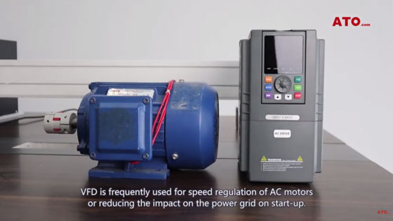
VFD is mainly composed of rectification (AC to DC), filtering, inverter (DC to AC), braking unit, drive unit, detection unit and micro-processing unit. The VFD adjusts the voltage and frequency of the output power supply by turning on and off the internal IGBT, and provides the required power supply voltage according to the actual needs of the motor, thereby achieving the purpose of energy saving and speed regulation. In addition, the inverter has many protection functions. Such as overcurrent, overvoltage, overload protection and so on. VFD is frequently used for speed regulation of AC motors or reducing the impact on the power grid on start-up.
Single phase to 3 phase VFD wiring
ATO 1-phase 220V to 3-phase 380V VFD (frequency inverter) is widely used in places where there is no three-phase electricity. The following teaches you how to wire.
Today ATO will introduce you a 1.5kW VFD220V single-phase input, 380V three-phase output.
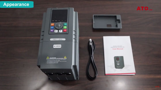
The packaging box would enclose an additional connecting wire as well as an instruction manual.
This is the control panel.

On the right side is the data plate.
The venting holes on the lateral side help with heat dissipation.
The fan on the back serves as the major heat- dissipating installation.

Mounting holes are placed on the four corners.
Control panels are available in different languages catering to the needs of users from different countries.
The control panel is convenient for dismantling and replacement.
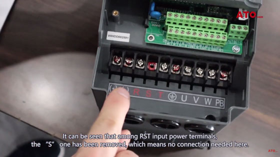
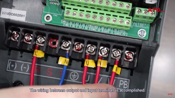
Open up the terminal box, it can be seen that among RST input power terminals, the "S" one has been removed, which means no connection needed here.
UVW is the motor's wiring terminal.
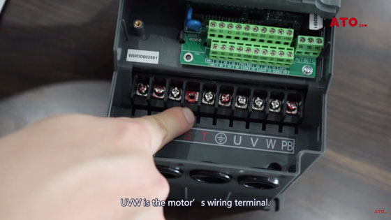
Terminals marked in red are optional for connection.
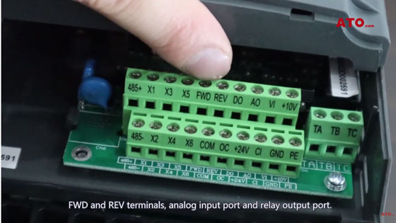
This is the control terminal which is equipped with RS485 port, X1 to X6 multi-functional terminal posts.
FWD and REV terminals, analog input port and relay output port.
Now we' re gonna connect the input terminal.
Wire terminals R and T.
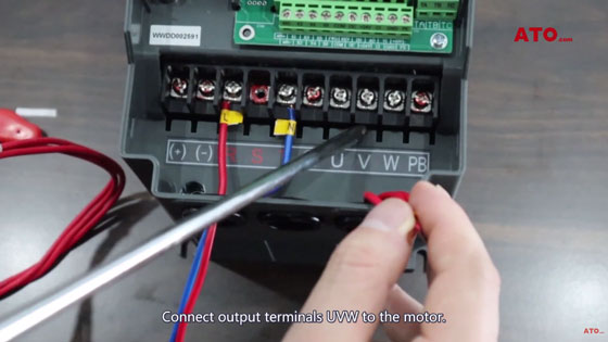
Connect output terminals UVW to the motor.
The wiring between output and input terminals is accomplished.
The input current of VFD is 220V single- phase and the VFD will transmit 380V three-phase current into the corresponding motor.
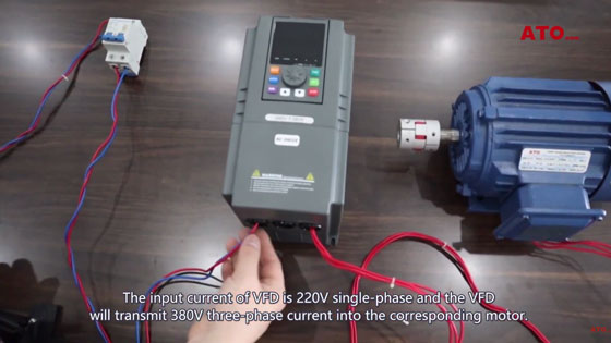
The overall appearance and basic wiring process are shown as above. If you still have questions about how the VFD connects to the motor, watch the video below.
