How Does the Limit Switch Control the Material Trolley Automatically?
Limit switches are used to control the travel and limit protection of mechanical equipment. In actual production, the travel limit switch is installed in a pre-arranged position. When the module installed on the moving parts of the production machinery hits the travel switch, the contacts of the travel limit switch act to realize the switching of the circuit. Therefore, the limit switch is an electrical appliance that switches the circuit according to the travel position of the moving part, and its working principle is similar to that of a button. Limit switches are widely used in various machine tools and hoisting machinery to control their travel and perform terminal limit protection. In the control circuit of the elevator, the travel limit switch is also used to control the speed of opening and closing the car door, the limit of automatic door opening and closing, and the upper and lower limit protection of the car.
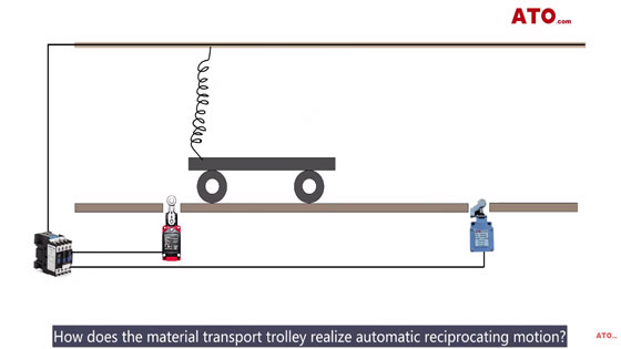
How does the material transport trolley realize automatic reciprocating motion?
Two limit switches control its movement.
Control logic
1. The contactor KM controls the forward and backward movement of the trolley (NO and NC contacts of the contactor control the forward or backward movement of the trolley).
2. Limit switches SQ1 and SQ2 control the coil of the contactor.
3. When the material trolley is pressed to SQ1, the trolley tops moving forward and then moves backward.
4. When the material trolley is pressed to SQ2, the trolley stops backward and then moves forward.
Control circuit
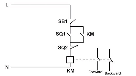
The limit switch controls the on and off of the contactor KM.
This is ATO limit switch.
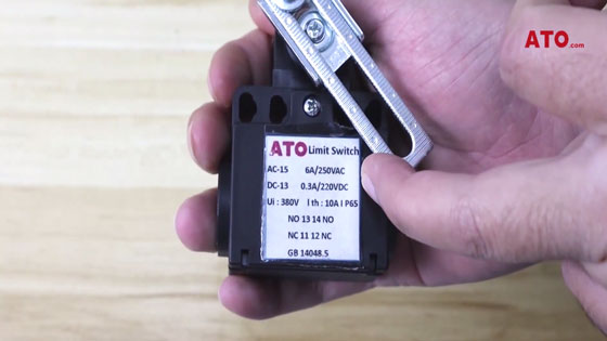
There are a set of NO contacts and a set of NC contacts in the limit switch.
The control system is mainly composed of: button switch, limit switch and contactor.
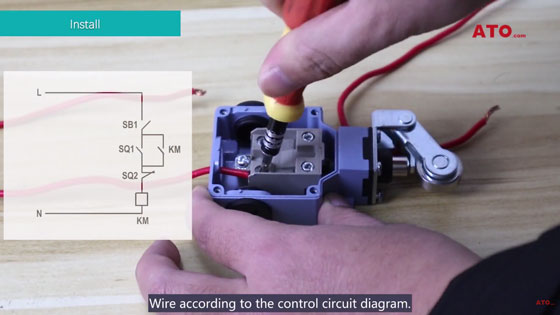
Wire according to the control circuit diagram.
A set of NO contacts self-lock the contactor.
The following group is the coil control circuit of the contactor

When the transport trolley runs to SQ1, press to the limit switch SQ1.
When the transport trolley runs to SQ2, press to the limit switch SQ2.
Such repetition will realize the automatic reciprocating movement of the material transport trolley.
ATO waterproof limit switches apply to AC-15, 5A/250VAC, 3A/125VAC. Its structures are: fork lever, adjustable rod lever, coil spring, top plunger, roller plunger, and adjustable roller lever. If you still have questions about how limit switches work, check out the video below:
