How to Drive a Brushed DC Motor?
When the brushed DC motor is working, the coil and the commutator rotate, but the magnetic steel and the carbon brush do not rotate. The alternating change of the current direction of the coil is accomplished by the commutator and the carbon brush that rotate with the motor. Compared with brushless motors, brushed motors have fewer wires, just one positive and one negative wire. If the BDC motor needs to be reversed, just switch the position of the two wires and it will be done. In the electric vehicle industry, brushed DC motors are divided into high-speed brushed motors and low-speed brushed motors.
Using an H-Bridge Circuit to Drive a Brushed DC Motor
A brushed DC motor has two power terminals, and the motor is driven by applying a voltage across these two terminals. The two terminals have the following four connection combinations:
- ① Neither terminal is connected anywhere. (The same applies when one is connected and the other is not.)
- ② Connect (+) of the DC power supply to one terminal and (-) to the other terminal.
- ③ Connect the DC power supply to the motor with the opposite polarity to ②.
- ④ Connect the two terminals.
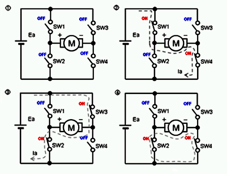
These four states can be achieved by thefollowing circuit using four switches. Because this circuit is shaped like the letter "H", it is called an "H-bridge circuit" (also known as "full-bridge circuit").
- In ①, the state where the power terminal is not connected to any place, it can be realized by turning off all SW1 to SW4.
- In ②, connect (+) of the DC power supply to one terminal and (-) to the other terminal, SW1 and SW4 need to be turned on (ON), and SW2 and SW3 should be turned off (OFF). This way the brushed DC motor will rotate in a certain direction.
- The connection method of ③ is opposite to that of ②. Turn SW1 and SW4 off (OFF), and turn SW2 and SW3 on (ON). In this way, the motor will rotate in the opposite direction to ②.
- ④ is the connection between the power terminals. When SW1 and SW3 are turned off (OFF) and SW2 and SW4 are turned on (ON), it is in a state where the terminals are connected to each other.
The circuit for changing the connection of the brushed DC motor
In the above diagram, switches are used to facilitate understanding of how the connections are combined, but in an actual electronic circuit, four switches use semiconductor power transistors. The configuration shown in the figure below is the actual H-bridge circuit. In this circuit, P-channel MOSFETs are used for the (+) side transistors (Q1, Q3) of the power supply, and N-channel MOSFETs are used for the (-) side transistors (Q2, Q4).
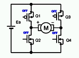
An actual drive circuit configuration
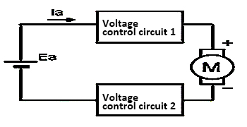
To change the speed of a brushed DC motor, it is necessary to change the voltage applied to the brushed DC motor. To do this, a voltage control circuit is inserted between the power supply and the brushed DC motor to directly or indirectly control the voltage applied to the brushed DC motor. There are two control methods, one is to directly connect the brushed DC motor on the (-) side, and the other is to insert a control circuit to control the (-) side at the same time. The actual drive circuit consists of an H-bridge circuit and a voltage control circuit that can change the connection state.
