How to Set Up a BLDC Motor Control Circuit Using RS485 Communication?
Controlling a Brushless DC (BLDC) motor via RS485 communication provides a highly precise, noise-resistant, and scalable method for industrial automation, robotics, and smart machinery. In this tutorial, we’ll walk you through how to set up a BLDC motor control circuit using RS485 communication, including how to connect and configure a BLDC motor controller with an RS485-to-USB converter for seamless PC-based motor control.
Components Required
For this setup, you will need the following components:
- BLDC Motor
- BLDC Motor Controller
- 24V DC Switching Power Supply
- RS485-to-USB Converter
- PC with BLDC Control Software
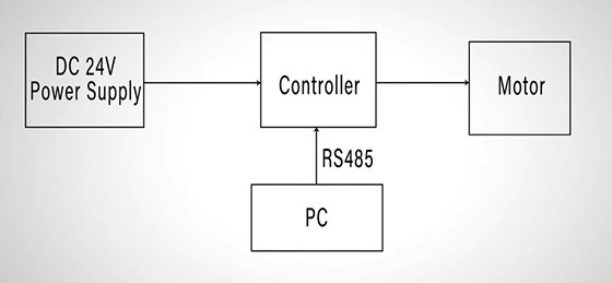
Among these components, the brushless DC motor requires the electronic controller to regulate its speed and direction. The 24V DC switching power supply is used to power the motor and controller, while the converter is intended to bridge communication between the controller and PC which has dedicated BLDC control software installed, responsible for sending speed commands via RS485. This control system allows precise speed adjustments without manual potentiometer tuning.
Circuit Diagram
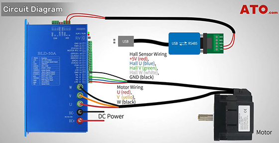
Now, let’s wire up the system correctly as per the wiring diagram provided. To correctly wire up the BLDC motor control system, start by connecting the 24V DC switching power supply to the designated power terminals on the controller. Next, connect the three-phase wires (U, V, W) from the BLDC motor to the corresponding output terminals on the controller, ensuring the phase sequence is correct. If your motor is equipped with built-in Hall sensors, connect them to the appropriate Hall input pins on the controller for position feedback. Finally, connect the RS485-to-USB converter to the RS485 communication terminals of the controller, ensuring the wiring polarity is correct—A to A+, and B to B–.
Controller Configuration
Before proceeding, configure the BLDC controller with the RV (potentiometer) terminal turned off —since we’re using RS485 for speed control, we don’t need manual adjustment. And set the two dip-switches SW1 and SW2 to OFF by toggling both switches up.
RS485 Communication Setup
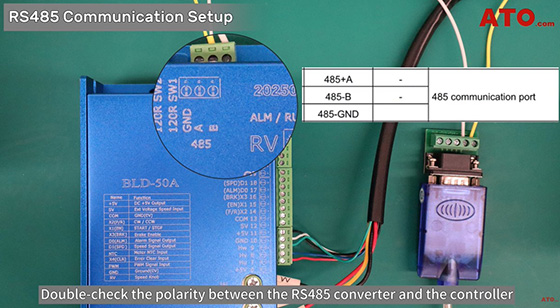
Double-check the polarity between the RS485 converter and the controller to avoid communication errors, with A to A+, B to B-. Then power on the system and plug the RS485 converter into your PC’s USB port.
Software Setup
Now, let’s configure the BLDC control software. Ensure your PC has the control tool installed correctly beforehand. Navigate to Com Setting, then click Connect. The software auto-detects the COM port (e.g., COM5) and baud rate (default: 38400). Upon successful connection, the software will start reading parameters. Once the reading is complete, this signifies the BLDC motor controller is successfully connected to your PC for RS485 communication. If connection fails, verify the port in Device Manager and confirm the controller’s address (default: 01).
Parameter Setting
To begin configuring the BLDC motor controller for RS485 communication, start by setting parameters PN14 and PN15 both to 2 under the Parameter Setting menu. Here, PN14 defines the Data Channel, and PN15 defines the Control Channel. Setting both to 2 enables MODBUS protocol control. In this setup, PN14 selects the SV analog input as the data source, while PN15 uses an I/O switch as the control signal input.
Next, set PN58 (Data A), which is the core parameter for controlling the motor’s speed and direction. According to the controller’s documentation, PN58 accepts values from 0 to 65535, and changes take effect immediately. RS485 will send these values as commands directly to the motor controller.
For example, if you want the motor to run clockwise at 300 rpm, simply enter 300 in the "New value" field and click Write param. The motor will respond instantly, and the positive value indicates forward (clockwise) rotation. You can monitor the real-time speed via the Device Information panel, particularly the Pn137-Speed parameter. If it’s not visible, click Refresh to update.
To make the motor run in reverse (counterclockwise), subtract the target speed from 65535 and input the result into PN58. For instance, reverse at 300 rpm = 65535 - 300 = 65235. Enter 65235 and hit Write param. You will notice PN137 still shows 300, but the motor runs in the opposite direction. Similarly, to run at 1,000 rpm in reverse, enter 65535 - 1000 = 64535. Forward motion at 1,000 rpm simply requires entering 1000.
You can also define the valid speed range using PN68 (maximum speed) and PN69 (minimum speed). In most default setups, this range is set between 200 and 3,500 rpm. If a value outside this range is entered, the controller will automatically limit it. For example, if you enter 100 rpm, the motor will default to 200 rpm. Likewise, entering 4,000 rpm will cap the speed at 3,500 rpm. These behaviors can be verified in Pn137-Speed. Finally, to stop the motor, set Data A (PN58) to 0. This will immediately halt the motor operation.
This concludes our demonstration on the RS485-based BLDC motor controller circuit. By leveraging this technology, you can achieve precise and seamless control of your BLDC motor system in automation, robotics and industrial applications. If you have any questions, you can watch the video below.
