
LCR Meter
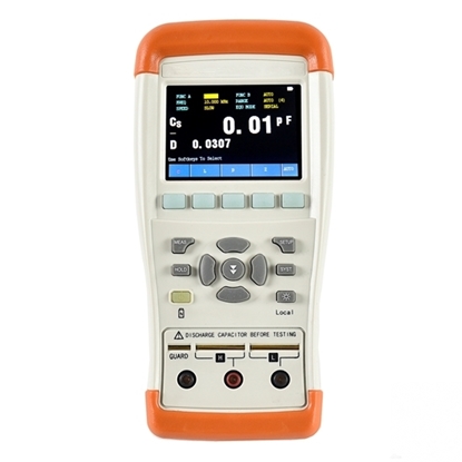
Handheld LCR Meter, 100Hz~100kHz
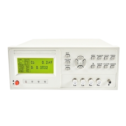
Digital LCR Meter, 50Hz~100kHz
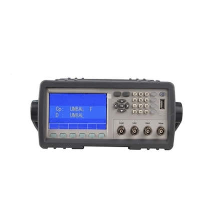
Digital LCR Meter, 50Hz~200kHz
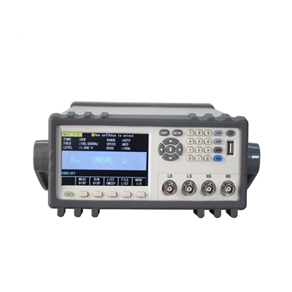
Digital LCR Meter, 20Hz~200kHz
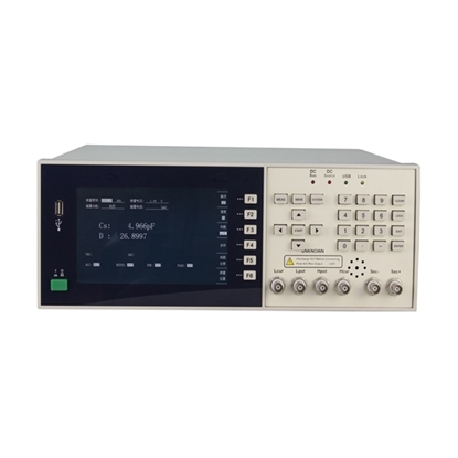
Digital LCR Meter, 20Hz~1MHz
An LCR meter, also known as an LCR bridge or digital LCR bridge, is an electronic measuring instrument used to precisely measure the inductance (L), capacitance (C), resistance (R), and impedance of electronic components. Operating on the auto-balancing bridge principle, it applies an AC test signal to a component to measure voltage-current amplitude and phase difference, calculating the impedance and derived values like quality factor (Q) and dissipation factor (D).
Supporting multiple test frequencies and series/parallel equivalent circuits, this highly accurate and user-friendly instrument is widely utilized across electronic component inspection, circuit maintenance, and R&D testing. Selecting the appropriate test frequency and equivalent circuit mode is essential for achieving accurate component characterization.
Key Applications of LCR Meters in Modern Electronics
- Advanced R&D & Materials Science: The LCR meter seamlessly bridges hardware design and materials science, delivering precise multi-frequency sweeps and complex impedance analysis (Z-θ) to validate SPICE simulation models, select ultra-low tolerance components, and characterize advanced substrate dielectric properties.
- High-Throughput Industrial Manufacturing: Instead of relying on manual testing, production facilities can easily scale quality control by integrating LCR meters into Automated Test Equipment (ATE) for high-speed component binning, high-throughput IQC/QA screening, and rapid PCB/PCBA defect isolation.
- Power Electronics & Systems Engineering: Perfectly suited for heavy electrical equipment and renewable energy systems, the LCR meter efficiently evaluates magnetic saturation, transformer winding DCR, and thermal degradation in high-power inverters, converters, and onboard chargers (OBC).
- Embedded Diagnostics & Circuit Maintenance Pair: Highly optimized for in-circuit troubleshooting and high-density PCB maintenance, the LCR meter provides accurate, low-level signal testing to detect ESR rise, isolate faulty SMD components, and monitor aging electrolytic capacitors without damaging sensitive circuitry.
LCR Meter Product Line Comparison
Explore the comprehensive ATO lineup of high-performance LCR meters, designed to deliver exceptional accuracy and versatile testing frequencies for every level of electronic component analysis. Compare the key specifications below to find the ideal model for your technical requirements.
| SKU | Type | Frequency Range | Basic Accuracy | Core Features |
| ATO-LCRM-1010 | Handheld | 100Hz ~ 100kHz | 0.20% | 32-bit ARM microprocessor, simultaneous main/secondary display, highly portable, and easy to use. |
| ATO-LCRM-5010 | Digital | 50Hz ~ 100kHz | 0.1% | Fast measurement speed, complete functions, suitable for various components with high cost-performance. |
| ATO-LCRM-5020 | Digital | 50Hz ~ 200kHz | 0.05% | High precision and wide testing range, applicable to all kinds of electronic components. |
| ATO-LCRM-2020 | Digital Bridge | 20Hz ~ 200kHz | 0.05% | High-performance compact bridge supporting 15 basic test specifications, including L, C, R, |Z|, D, Q, |Y|, G, X, RDC, etc. |
| ATO-LCRM-20100 | Digital Bridge | 20Hz ~ 1MHz | 0.05% | Flagship multifunctional bridge supporting advanced level, frequency, and offset scanning; simple operation. |
FAQs of LCR Meters
Optimize your component testing with this essential LCR meter FAQ. Learn to perform open/short calibrations, choose between series and parallel circuits, and use Kelvin connections to minimize impedance measurement errors.
Q1: What is the standard measurement workflow for an LCR meter?
A: Configure your test frequency and parameters, perform open/short calibrations to eliminate fixture errors, connect the matched fixture to your component, and begin testing.
Q2: How do I choose between Series (s) and Parallel (p) equivalent circuit models?
A: Use the Series model for low-impedance components(|ZX| < 10 Ω, like large capacitors) and the Parallel model for high-impedance components(|ZX| > 10 kΩ, like small capacitors).
Q3: What environmental conditions and warm-up time are required for accurate LCR meter operation?
A: Maintain an operating temperature of 0–40°C and humidity ≤ 90% RH, allowing a 10 to 30-minute warm-up time away from strong magnetic fields to stabilize internal LCR meter circuitry.
Q4: What is the recommended LCR meter connection method to reduce measurement errors?
A: Use a four-terminal pair (Kelvin connection) fixture or specialized test leads tailored to the component’s packaging style (e.g., SMD vs. axial-leaded) to minimize contact resistance.
Q5: What critical open/short calibration, maintenance, and battery precautions should I follow?
A: It is highly recommended to run open/short calibration before testing to prevent signal overload, clean fixture contacts regularly, and remove batteries during long-term storage or when using external power.
