PLC Pulse Control Stepper Motor
stepper motor, pulse and direction signal
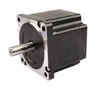
As a common electrical actuator, stepper motor is widely applied in automatic control field. Stepper motor needs to be equipped with a special drive power the output of which is controlled by external pulse signal and direction signal. Each pulse signal can make stepper motor rotate a fixed angle, which is called step angle. Total angle and speed of rotation respectively depend on the number and frequency of pulse. The direction of rotation depends on direction signal. For a equipment with a known transmission ratio, the movement distance and speed of its parts can be controlled by controlling the number and frequency of pulse without the requirements for the feedback of distance and speed signals; and direction signal can control moving direction. Therefore, open loop control is a simple and economic electronic control technical scheme.
 In addition, the subdivision operation mode of stepper motor is very practical. Step angle can’t be small owing to the limit of mechanical manufacturing, but the rotation of stepper motor can be achieved by dividing one step into m steps through electric control which will improve the accuracy and stability of equipment operation.
The pulse and direction signals controlling the power supply of stepper motor generally adopt numerical control system, but PLC is an ideal technical scheme for the equipment with the known movement distance and speed in operation.
Control scheme
Distance, speed and direction are controlled by setting movement distance, speed and direction on operation panel and controlling the drive power of stepper motor through pulse and direction signals produced by the operation of PLC. Movement distance, movement speed, movement direction and start and stop are respectively controlled by position button, speed button, direction button and start/stop button on operation panel.
In real system, position and speed are generally divided into several gears, so position knob and speed knob can choose band switch which can reduce the number of connection lines between operation panel and PLC, the number of input points of PLC and costs by encoding wire jumpers. The highest gear of one n-knife band switch is 2nth gear.
Refer to pulse equivalent, upper limit of pulse frequency and maximum number of pulse of following calculating system before PLC model selection.
The needed frequency in the output of high-speed pulse of PLC and bit width of PLC can be determined respectively according to the frequency and number of pulse. Meanwhile, PLC should choose the output type of transistor considering the timeliness, reliability and service life of system response.
The resonant frequency of motor should be avoided in the choice of subdivision number of stepper motor, generally 2, 5, 10 and 25. In PLC control programming, the pulse equivalent and reverse gap of drive system and subdivision number of stepper motor should be defined as parameter variables for the convenience of site adjustment.
