What is a Non-encolsure VFD for Custom-made Equipment?
Customized equipment, also known as non-standard equipment, is a type of integrated automated equipment that is specifically designed as customers desire and not circulating on the market. In this video, we’re gonna show you a non-enclosure VFD that is specially built for custom-made equipment.
Our non-enclosure VFD includes a keypad, a communication cable and a body which consists of a main circuit board and a cooling module with a fan. These separate components can be installed where necessary such as self-designed electrical cabinets, consoles, integrated equipment, etc.

What’s the differences between standard and non-enclosure VFDs?
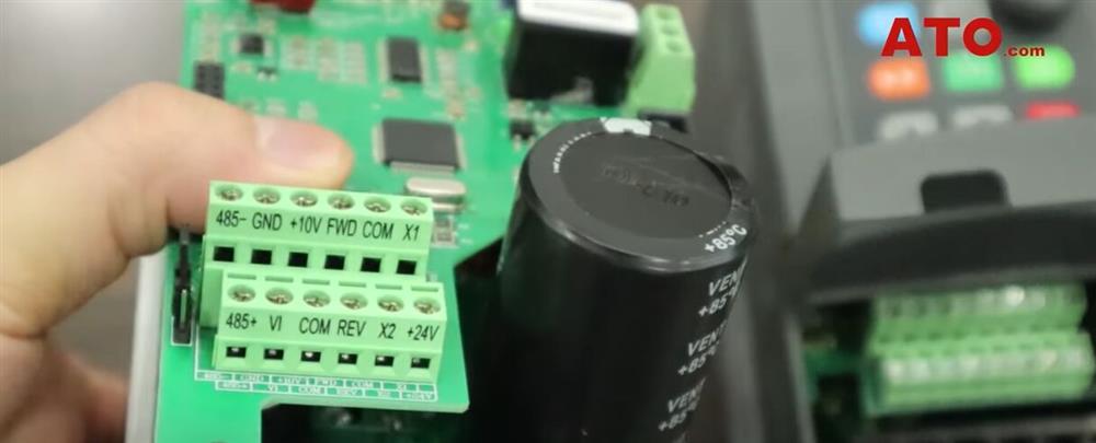
- The control terminal arrangements: The non-enclosure VFD has a relatively small number of wiring terminals which include RS485 terminals, analog terminals, forward-reverse control ports, two custom input terminals, X1 and X2, along with an input port for 24V power supply. The relay alarm output terminals are arranged on the right edge of the main circuit board.
By contrast, the standard VFD has a bit more terminals than the non-standard one. In addition to those on the non-enclosure VFD, it has two extra custom terminals, X3 and X4, and terminal GND for grounding and another 10V analog terminal is added. The relay alarm output terminals are located in close proximity.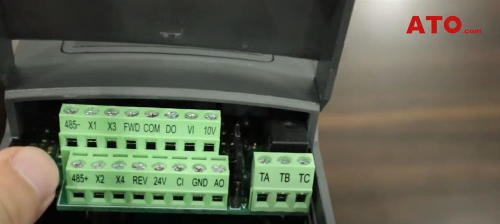
- The wiring ports on the main circuit: The non-enclosure VFD has six ports that are designed for different use. the Line and Neutral terminals are intended for wiring single phase AC power supply, and this is the Earthing terminal. The U, V, W ports are used for wiring the motor.
As to the standard VFD, there are seven holes made on the shell and each hole is coded according to the purpose of each terminal behind. Be aware that there is actually six terminals behind the holes since the L3 terminal is removed to prevent accidental connection. As is labeled on the shell here, for single phase power input, you need to connect L1 and L2. And as we said before, E terminal for grounding and U, V, W for motor wiring. The cooling modules of both VFDs are basically the same in terms of construction. They both have several pieces of cooling fins as well as a cooling fan except that the standard VFD has its capacitor located beside the cooling module while the non-enclosure VFD has its comparatively larger capacitor placed on the bottom right corner of the main circuit board.
How to connect the VFD to a 3-phase motor?
We use ATO-IM-7504P here for the demonstration. It’s 750W rated and with 220V and 380V optional voltage ratings. As our VFD is rated at single phase 220V for input and three phase 220V for output, we should make sure the motor is rated at the same voltage. For this, we need to uncover the wiring part of the motor and check its specific wiring pattern.
Step 1: Wiring
- Uncovering the wiring part of the motor and check its specific wiring pattern.
- Taking a Phillips head screwdriver, loosen the screws on the faceplate and remove the faceplate from the body housing.
You will notice that there is a wiring diagram on the back of the faceplate and as is shown, it’s a 220V rated motor. Then take the screwdriver and tighten the screws on the faceplate. - Inserting the wires from the motor into the U, V, W terminal screws. Make sure you properly tighten each terminal after inserting each wire. Connecting the power wires to the line and neutral terminals the exact same way. The power supply used here is surely rated at 220V as specified.
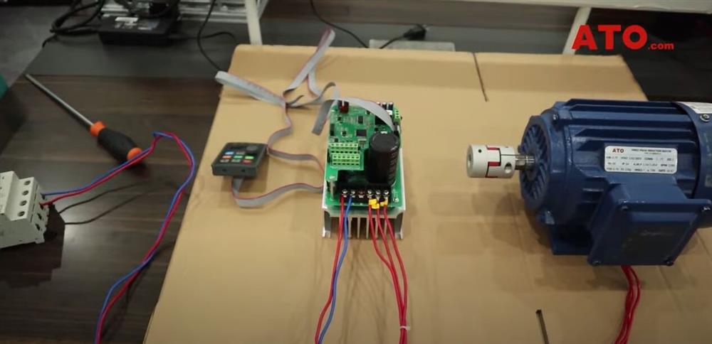
So here we have it completely wired where the VFD output terminals are connected to the motor and the keypad is connected to the VFD via the communication cable.
Step 2: Power up the whole circuit.
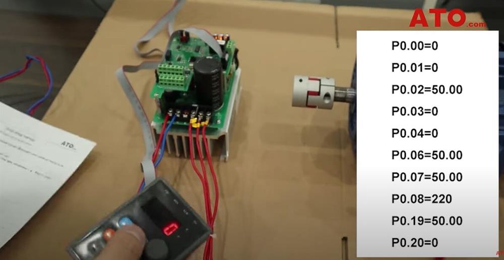
- Setting the parameters. Be sure to reference the instruction manuals included to set up the parameters and it’s quite easy to do so on the keypad. Check previous videos about the standard VFD to learn how to set parameters on the non-enclosure VFD as both share the same setting method.
- Pressing START on the keypad and the motor starts running.
- Turning the knob on the keypad to adjust the frequency so as to change the rotation speed of the motor.
Besides starting the VFD through the keypad, we can also control it via Modbus-RTU, analog as well as external terminals.
If you want to know more details about the non-encolsure VFD for custom-made equipment, please click the video below.
