What is an OTDR and How Does It Work?
The full name of OTDR is Optical Time Domain Reflectometer. An optical time-domain reflectometer (OTDR) is an optoelectronic instrument used to characterize an optical fiber. It is the optical equivalent of an electronic time domain reflectometer. OTDR is widely used in the maintenance and construction of optical cable lines, and can measure optical fiber length, optical fiber transmission attenuation, joint attenuation and fault location.
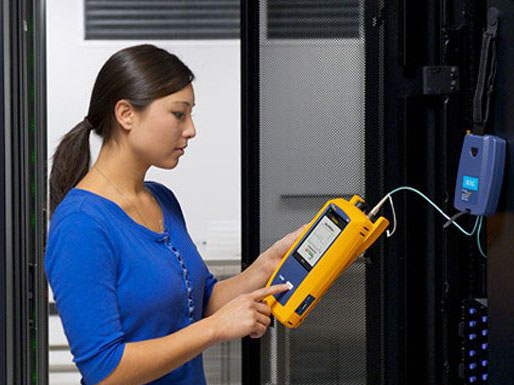
Fiber optic cable testing is an important technical means for optic cable construction, maintenance, and emergency repair. The use of OTDR (Optical Time Domain Reflectometer) for on-site monitoring of fiber optic connections and connection loss measurement and evaluation is currently the most effective way. This method is intuitive, credible and can print the fiber backscattered signal curve. In addition, the actual transmission distance from the intra-office to each joint point can be accurately measured while monitoring, which is very necessary to accurately find faults and effectively deal with faults during maintenance. At the same time, maintenance personnel are required to master the performance of the instrument, be skilled in operation, and accurately judge the characteristics of the signal curve.
OTDR Working Principle
OTDR testing is performed by transmitting light pulses into the fiber and then receiving the returned information at the OTDR port. When a light pulse is transmitted within an optical fiber, scattering, reflection occurs due to the nature of the fiber itself, connectors, splices, bending or other similar events. Part of the scattering and reflection is returned to the OTDR. The useful information returned is measured by the OTDR's detectors as time or curve segments at various locations within the fiber. The time taken from the emission of the signal to the return of the signal determines the speed of the light in the glass material, then the distance can be calculated.
d= (c×t) / 2 (IOR)
Where c is the speed of light in a vacuum, and t is the total time after the signal is emitted until the signal is received. Because light travels slower in glass than in vacuum, the fiber being measured must have an index of refraction (IOR) specified in order to measure distances accurately. The IOR is specified by the fiber optic manufacturer.
OTDR uses Rayleigh scattering and Fresnel reflection to characterize the fiber. Rayleigh scattering is caused by random scattering of the optical signal along the fiber. The OTDR measures a portion of the scattered light back to the OTDR port. These backscattered signals indicate the degree of attenuation (loss/distance) caused by the fiber. The resulting trace is a downward curve that illustrates the decreasing backscattered power due to the loss of both transmitted and backscattered signals over a distance.
Fresnel reflections are discrete reflections caused by individual points throughout the fiber, which are made up of factors that change the inversion coefficient, such as the glass-air gap. At these points, strong backscattered light is reflected back. Therefore, OTDR is to use the information of Fresnel reflection to locate the connection point, fiber termination or breakpoint.
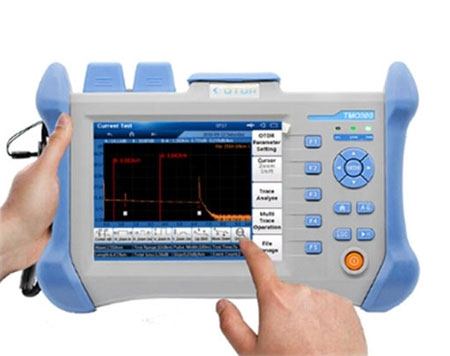
An OTDR works like a radar. It first sends a signal to the fiber, and then observes what information is returned from a certain point. This process is repeated, and the results are averaged and displayed as a trace, which depicts the strength of the signal (or the state of the fiber) throughout the length of the fiber.
OTDR Main Performance Index
Knowledge of the OTDR's performance parameters helps in practical fiber measurements. OTDR performance parameters mainly include dynamic range, dead zone, resolution, accuracy, etc.
Dynamic Range
Dynamic range is one of the main performance indicators of an OTDR, which determines the maximum measurable length of an optical fiber. The larger the dynamic range, the better the curve shape and the longer the measurable distance. Currently, there is no unified standard calculation method for dynamic range. Following are four commonly used definitions of dynamic range:
- IEC definition (Bellcore): One of the commonly used dynamic range definitions. Take the dB difference between the backscattering level at the beginning and the peak noise level. The measurement conditions are the maximum pulse width of the OTDR and the measurement time of 180 seconds.
- RMS definition: the most commonly used dynamic range definition. Take the dB difference between the backscatter level at the start and the RMS noise level. If the noise level is Gaussian, the RMS definition is about 1.56dB higher than the IEC definition.
- N=0.1dB definition: the most practical definition method. Take the maximum allowable attenuation value that can measure an event with a loss of 0.1dB. The defined value of N=0.1dB is about 6.6dB smaller than the defined value of RMS of SNR=1, which means that if the OTDR has a RMS dynamic range of 30dB, the dynamic range defined by N=0.1dB is only 23.4dB, that is, only Events with a loss of 0.1dB are measured over a range of 23.4dB attenuation.
- End detection: The dB difference between the 4% Fresnel reflection peak at the beginning of the fiber and the RMS noise level, this value is about 12dB higher than the IEC defined value.
Blind Zone
Blind zone (also known as dead zone), refers to the part of the OTDR curve that cannot reflect the state of the fiber optic line within a certain distance range due to the influence of Fresnel reflection. This phenomenon occurs mainly because the strong Fresnel reflection signal on the optical fiber link saturates the photodetector, which requires a certain recovery time. Dead zones can occur at slip-knots in front of the OTDR panel or other places in the fiber link where there are Fresnel reflections.
Bellcore defines two types of dead zones: attenuation dead zone (ADZ) and event dead zone (EDZ). The attenuation dead zone refers to the minimum distance between two reflection events when the respective losses can be measured separately. Usually, the attenuation dead zone is 5 to 6 times the pulse width (represented by distance); the event dead zone refers to the two reflection events that are still distinguishable. Minimum distance, where the distance to each event is measurable, but the respective loss of each event is unmeasurable.
The size of the blind zone is related to the pulse width, reflex coefficient, loss and other factors. The shorter the pulse width, the smaller the dead zone, but the short pulse reduces the dynamic range at the same time. Therefore, the pulse width should be compromised between the dead zone and the dynamic range.
Resolution
OTDRs have four main resolution metrics: sampling resolution, display resolution (also called readout resolution), event resolution, and distance resolution. Sampling resolution is the minimum distance between two sampling points, which determines the OTDR's ability to locate events. The sampling resolution is related to the selection of pulse width and distance range. Display resolution is the smallest value that the instrument can display. The OTDR subdivides each sampling interval through the microprocessor system, so that the cursor can move within the sampling interval. The shortest distance of the cursor movement is the horizontal display resolution and the displayed minimum attenuation amount of the vertical display resolution.
Event resolution refers to the OTDR's resolution threshold for the event points in the link under test, that is, the event threshold (detection threshold). The event resolution is determined by the photodiode's resolution threshold, which specifies the minimum attenuation that can be measured based on two close power levels. Distance resolution refers to the shortest distance between two adjacent event points that the instrument can distinguish. This index is similar to the event blind zone, and is related to the parameters of pulse width and refractive index.
Accuracy
Accuracy is how close the OTDR's measurement is to the reference value, including attenuation accuracy and distance accuracy. The attenuation accuracy is mainly determined by the linearity of the photodiode. At present, the linearity of most OTDRs can reach 0.02dB/dB. The distance accuracy depends on the refractive index error, time base error and sampling resolution. When the refractive index error is not considered, the distance accuracy can be expressed by the following formula:
Distance accuracy=±1m±5×10⁻⁵×distance±sampling resolution
Well, so much for the introduction of OTDR. If you like this article, please leave us a comment.
