What is the Current Transformer Tester working Principle?
In the realm of electrical systems advocates for current transformer (CT) testing at frequencies lower than the rated frequency. This approach aims to prevent undesirable voltages across windings and secondary terminals. This blog post explores the working principles of low-frequency testing, as outlined in the standard, shedding light on the CT voltage-current characteristics measurement circuit.
Low-frequency test principle
The CT test can be performed at a lower frequency than the rated frequency to avoid the winding and secondary terminals from being subjected to unacceptable voltages.
The principle circuit of CT volt-ampere characteristic measurement is as follows: the primary side of the CT is open, voltage is applied from the secondary side, and the relationship between the applied voltage V and the input current I is measured. This curve approximates the relationship between the excitation potential E and the excitation current I of the CT.
Suppose the excitation inductance of the CT excitation winding at a certain excitation current I is L and the excitation impedance is Z, then:
V = I·Z
The relationship between inductance L and impedance Z is as follows:
Z = ω·L = 2 π f L
Then: V= I·2 π f L
It can be seen from the formula that the applied voltage V is proportional to the frequency f at a certain exciting inductance L.
Assume that when f = 50Hz, in order to achieve the excitation current Ix, the required applied voltage Vx is 2000V
Vx = Ix·2 π f L = 2000V,
If different frequencies are applied:
f = 50Hz, Vx = 2000V
f = 5Hz, Vx ≌ 200V
f = 0.5Hz, Vx ≌ 20V
It can be seen that the CT needs to be brought into the same saturation level, and the voltage required to apply a lower frequency signal can be greatly reduced. This is the basic principle of the frequency conversion method.
It must be strictly noted here that the required voltage is not linearly proportional to frequency, nor does it decrease proportionally with frequency. A complete theoretical calculation needs to be carried out strictly in accordance with the precise mathematical model of the transformer.
Calculation and application method of 10% error curve
The error of the current transformer is mainly due to the existence of the excitation current, which makes the secondary current and the primary current converted to the secondary side not only unequal in value, but also in phase, which results in the error of the current transformer. .
The ratio difference of current transformers is defined as:
Relay protection requires that when the primary current of the current transformer is equal to the maximum short-circuit current, the ratio difference is less than or equal to 10%.
How to apply the 10% error curve:
CTP is used for the actual wiring methods of various CTs
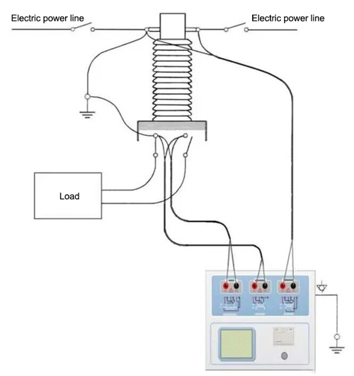
The basic wiring steps of CTP for CT testing (see Figure C.1) are as follows:
(1) Use 4mm2 wire to connect the ground terminal on the left side of the tester to the protective ground.
(2) Connect one terminal on the primary side of the CT and one terminal on the secondary side to the protective ground.
(3) Make sure that all other terminals of CT are disconnected from the power lines and all other windings are open circuit.
(4) Use 2.5mm2 red and black wires to connect the secondary side of the CT to the tester "Output" S1 and S2 jacks, and use 1.2mm2 yellow and black wires to connect the secondary side of the CT to the tester "Sec" S1 and S2 jacks, please note that the two black wires are connected to the same terminal on the secondary side of the CT that is connected to the protective ground.
(5) Use 1.2mm2 green wire and black wire to connect the primary side of the CT to the P1 and P2 terminals of the tester's "Prim". P2 is connected to the terminal where the primary side of the CT is connected to the protective ground through the black wire.
(6) Check that the wiring is correct and start testing.ct
Figure 1 Typical wiring method
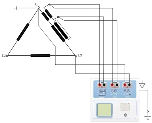
The wiring method of the tester for CT testing on the delta connection transformer is shown in Figure 2.
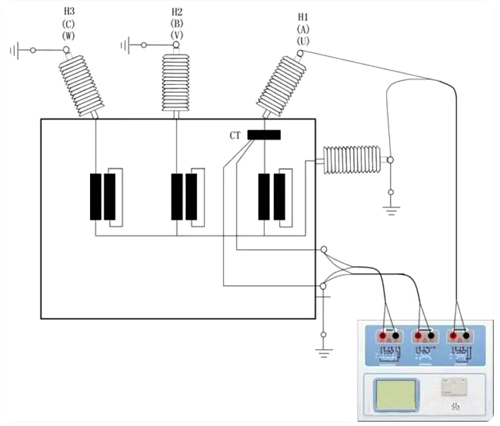
The wiring method of the tester when performing CT testing of transformer bushings is shown in Figure 3.
Note: Primary terminal H1 cannot be grounded, otherwise the tester will not be able to obtain correct results if both primary sides are grounded.
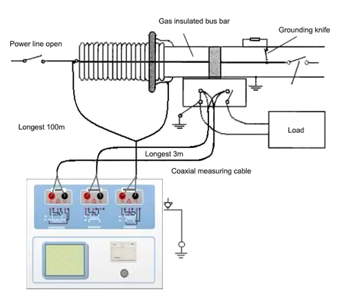
The wiring method of the tester when testing the CT on the GIS (SF6) switch is shown in Figure 4.
Note: Disconnect all switches connected to the busbar and close the grounding switch.
Measurement principle of four-terminal wiring
Applying and outputting a voltage source signal Vs to an impedance R will generate a current I, as shown in the figure.
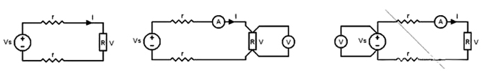
If you need to measure the impedance value, you need to measure the voltage V on the impedance:
Since there is a section of wire from the voltage source to the impedance being measured, the wire has resistance r, resulting in V=Vs. Therefore, if you want to accurately measure the impedance R, you cannot simply use the power supply voltage Vs instead of V.
The measurement circuit of impedance R should adopt the wiring method in Figure D.2. The voltmeter for measuring voltage must be connected with separate wires from both ends of R to accurately measure the voltage value V of R. Since both ends of R are connected using 4 wires, it is called 4-terminal wiring. The wiring method in Figure D.3 is wrong.
When using CTP to measure the resistance, transformation ratio, and excitation of a transformer, the 4-terminal method must be used for wiring.
When using the four-terminal method, attention must be paid to the terminal connection method of the winding under test. The correct connection method is shown in the figure below.
For more knowledge about the principles, please go to the ATO.com.
