How Does a Stepper Motor Work?
A stepper motor is a motor that converts electrical pulse signals into corresponding angular displacement or linear displacement. Each time a pulse signal is an input, the rotor rotates an angle or advances one step. Its angular displacement or linear displacement is proportional to the number of input pulses, and the rotational speed is proportional to the pulse frequency. Therefore, ATO stepper motors are also called pulse motors.
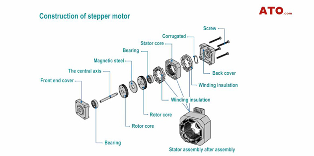
Construction of stepper motor
Stepper motor working principle
A Stepper motor is an open-loop control element stepper motor that converts electrical pulse signals into angular displacement or linear displacement. By controlling the sequence, frequency and number of electrical pulses applied to the motor coils, it can realize the steering, speed and rotation angle control.
The difference between unipolar winding and bipolar winding form
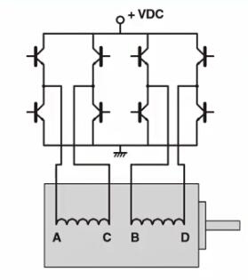
Take a two-phase stepper motor as an example. It has two winding forms: bipolar and unipolar. There is only one winding coil on each phase of a bipolar motor. When the motor rotates continuously, the current must be changed directionally in the same coil for excitation. The design of the drive circuit requires eight electronic switches for sequential switching.
There are two winding coils with opposite polarity on each phase of a unipolar motor. When the motor continuously rotates, it only needs to alternately energize and excite the two winding coils in the same phase.
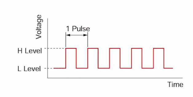
What is a pulse signal?
The pulse signal is an electrical signal whose voltage repeatedly changes between ON and OFF Each ON/OFF cycle is recorded as a pulse, and a single pulse signal command makes the motor output shaft rotate one step. The signal levels corresponding to the voltage ON and OFF are called “H” and “L” respectively.
Rotation distance is proportional to the number of pulses. The rotation distance of the stepper motor is proportional to the number of pulse signals (pulse number) applied to the drive. The relationship between stepper motor rotation (rotation angle of motor output shaft) and pulse number is as follows:
- θ=θsxA (Rotation angle of motor output shaft angle)
- θs (Step angle) (angle/step)
- A (Number of pulses)
The speed is proportional to the pulse frequency. The speed of the stepper motor is proportional to the frequency of the pulse signal applied to the driver. The relationship between motor speed [r/min] and pulse frequency [Hz] is as follows:
- N=θs/360xfx60
- N: Motor output shaft speed (r/min)
- θs: Step angle (angle/step)
- f: Pulse frequency (Hz)
One of the important features of stepper motors is high torque and small size. These features make the motors have excellent acceleration and response, making these motors very suitable for applications that require frequent starts and stops. MOONS' also has a motor with a gearbox to choose from to meet the demand for higher torque at low speeds.
When the winding is energized, the stepper motor has the full holding torque. This means that the stepper motor can remain in the stopped position without using mechanical brakes.
You can watch the video below to know more details about how to wire and test the stepper motor.
