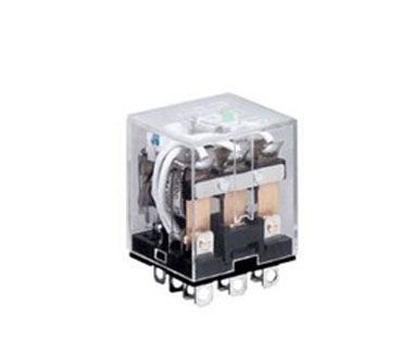
How to Improve the Reliability of a Relay?
Tue, Jul 17 by ATO.com
 In addition to comprehensive parameter testing and effective screening of relays, proper use of relays is also an effective way to improve the reliability of relays. Conversely, improper use will shorten the life of the relay. How to improve the reliability of the relay? Here are some suggestions for your reference.
- Reasonable selection of the working voltage of the relay
The pull-in voltage of the relay is generally only one-half to two-thirds of its rated working voltage. However, when using the relay, it must work at its rated working voltage, but not the pull-in voltage as the working voltage. This is because, under the condition of the pull-in voltage, although the relay has been operated, the pressure between the moving contacts has not reached the specified value, which will cause the contact resistance between the contacts to be too large, if the contact at high current conditions, when working, it will increase the contact power, which will easily lead to contact ablation and shorten the working life. - The use of no current switching
Although the allowable contact power is given in the technical specifications of the relay, and the corresponding electrical life is also given, the contact of the relay is allowed to be switched on, but the contact charging should be avoided as much as possible. No current switching will greatly increase the life of the relay. - Avoid using relays under low level and micro current
Because the relay has a low-level failure mode, the relay contacts should be avoided to operate at low level and micro current. Suitable solid state relays and analog electronic switches can be used instead of relays where possible. Reed relays can be used when the relay must be switched to low level and micro current, because the reed relay seals the contacts in the glass tube and the windings are outside the glass tube. This is in contrast to general purpose relays that seal the contacts to the windings in the same housing, which significantly reduces the likelihood of the contacts producing a passivation film that can cause low-level failure. - The relay fire extinguishing line
The winding of the relay is an inductor, and there is an armature in the winding. Therefore, the magnetic energy is stored after the winding is energized, and the magnetic energy release generates a high back potential (sometimes up to several hundred volts) when the winding is de-energized. On the one hand, this back-potential easily breaks down the devices that drive the relays (such as transistors and integrated circuits), and on the other hand, it causes spike interference and interferes with the normal operation of the whole machine and other lines in the system. The simplest solution to this problem is to connect a reverse-reverse diode (also called a freewheeling diode) in parallel with the winding of the relay. However, it should be noted that the addition of the anti-reverse diode will significantly extend the release time of the relay. - Parallel use of relay contacts
When a relay is required to switch a large current, try to use a relay with a large contact current instead of a parallel connection (whether it is a multiple set of contacts of one relay or a parallel connection of multiple relays). This is because it is difficult to ensure that the contact resistance is the same for each set of contacts of the relay, and uneven current distribution is likely to occur in parallel use. In addition, it is difficult to ensure the consistency of the contact action time, so that the instantaneous current of a certain group of contacts is likely to be excessive at the switching instant.
