How to Install a Constant Pressure Water Pump?
VFD constant pressure water pump
Process
- Understand the working principle
- Understand the workflow
- Prepare materials
- Wiring & installation
- VFD settings
- Run
Working principle
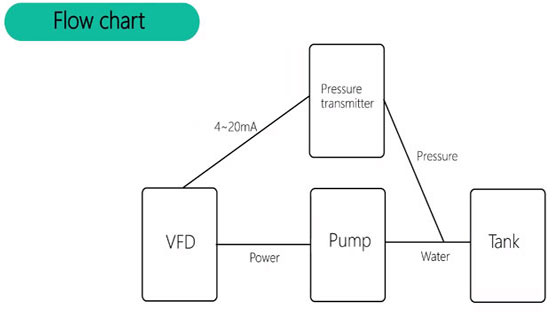
- The VFD drives the water pump, and the pressure sensor/transmitter feeds back the pressure signal to the VFD to form a closed loop system.
- When the water pipe pressure is less than the set value, the VFD wakes up and starts pumping water.
- When the pressure does not reach the set target, the operating frequency will continue to increase to the rated frequency of the pump.
- When the pressure is greater than the set pressure, the operating frequency will decrease.
- When the pressure is greater than the sleep pressure, the frequency decreases to the sleep frequency for a period of time, and then stops pumping water.
- When the pressure is lower than the wake-up pressure, the pump starts to run again.
Flow chart
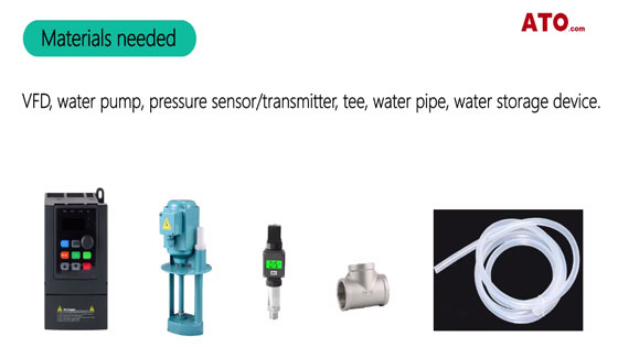
Materials needed
VFD, water pump, pressure sensor, tee, water pipe, water storage device.
Simulation wiring
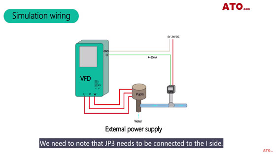
We need to note that JP3 needs to be connected to the I side. The pressure sensor output signal (green) is connected to VFD CI. Then, connect red line to 24V.
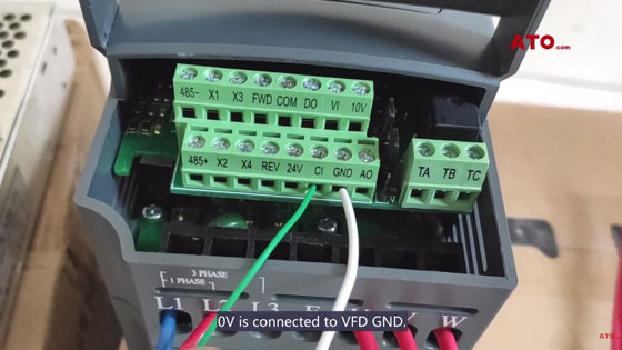
OV is connected to VFD GND.
VFD Setting
- P7.00= 1 (Close loop running)
- P7.01=0 (Close loop given channel selection,
- P7.05 Digital given + panel▲, ▼Fine tuning)
- P7.02 = 6 (Feedback channel selection, CI analog input (4~20mA) )
- * P7.05 = 0.035 (Target pressure, MPa)
- P7.19 = 0.008 (Wake up pressure, MPa)
- P7.20 = 0.040 (Sleep pressure, MPa)
- P7.22 = 30 (Sleep running, Hz)
- P7.26= 1 (One pump constant pressure water supply mode)
- P7.27 = 1 (Remote pressure gauge range, MPa)
- P7.10= 2 (Proportional integral control)
- P7.11= 5 (Proportional gain KP automatic speed adjustment)
- P0.17 = 3 (Acceleration time)
- P0.18= 3 (Deceleration time)
The ATO VFD needs to set the above parameters.
The key parameter is P7.05. (target parameter)
Run, when the pressure sensor does not reach the target pressure, the VFD operating frequency will gradually increase.
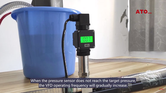
Up to the maximum frequency of rated operation.
When the frequency rises (when the pump accelerates pumping), the pressure in the pipe increases, and the rise of the VFD operating frequency slows down or decreases.
When the pressure is greater than the sleep frequency P7.20, the VFD will drop to the sleep frequency P7.22.
When the sleep time is complete, the VFD enters the sleep state.
If you want to know more detailed steps to install the constant pressure water pump, please watch the video below:
