How to Convert Analog Quantity into Digital Signal with Data Acquisition?
Data acquisition is an interface that uses a device to collect data from outside the system and input it into the system. Data acquisition technology is widely used in various fields. For example, cameras and microphones are all data collection tools.
The collected data are various physical quantities that have been converted into electrical signals, such as temperature, water level, wind speed, pressure, etc., which can be analog or digital. The data acquisition is generally a sampling method, that is, the data of the same point is repeatedly collected at a certain time interval (called a sampling period). Most of the collected data are instantaneous values, but also a characteristic value within a certain period of time. Accurate data measurement is the foundation of data collection. Data measurement methods are contact and non-contact, and there are various detection elements. Regardless of the method and component, the premise is that it does not affect the state of the measured object and the measurement environment to ensure the correctness of the data. The meaning of data acquisition is very broad, including the acquisition of continuous physical quantities in the form of planes. In computer-aided drafting, surveying, and design, the process of digitizing graphics or images can also be called data acquisition. At this time, data of geometric quantities (or including physical quantities, such as grayscale) are collected.
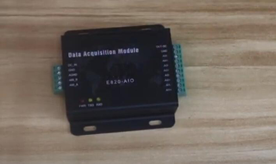
Today we are going to carry out data acquisition E820-AIO performance test.
Wiring
This data acquisition supports RS485 connection and Modbus RTU protocol. Collecting 4 channel analog quantity, with more reliable and better hardware protection. It satisfy industrial grade high precision analog acquisition order. It widely applied to intelligent agriculture, flood prevention, engineering measurement and transportation.
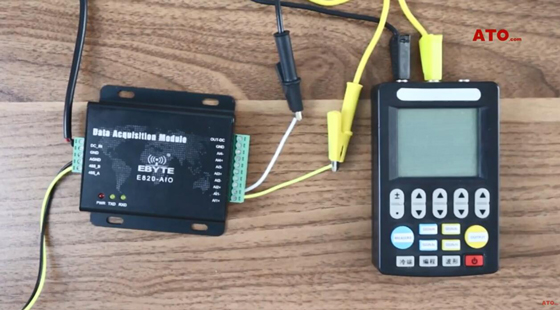
I will connect the equipment’s follow the circuit diagram. You should remember the number of communication port. Switch on the power supply.
Start Run
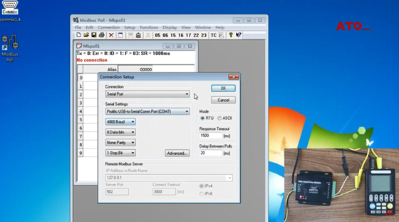
- Run the debugging software.
- Open the port, confirm the E820-AIO address.
- Write the command.
- Send.
- Transmission time is very fast communication success.
- The address of E820 is 01.
- Close port and close software.
- Operate the Modbus poll software.
- Connect. So that’s correct, parameter.
- We will confirm, there just is 0, 1.
- Change the status, off to on. The range of E820 is four to twenty mA. Mean, signal 4 mA is 0 input.
- Now we can see, the interface is showing 4978.
- Increase continuous.
- Let’s move to measurement, 20 mA. Now here is showing 19981.
- Close software and switch off the power supply.
View the video below to learn more details about analogue to digital converter / field data collector test.
