How to Set Up VFD V/F Control and Vector Control?
The difference between V/F control and vector control
VFD adopts V/F control mode or vector control mode. The variable frequency motor it drives is very different from ordinary motors, and the frequency range suitable for this motor is also very large, so long-term low-frequency operation of VFD is not harmless to the inverter, but in the long-term low-frequency operation of the inverter, it must be fully considered that its installation environment and ventilation performance are relatively good. As shown below.
Variable Frequency Drive changes the voltage of the motor power supply while changing the frequency of the motor power supply, so that the magnetic flux of the motor is kept constant, and the efficiency and power factor of the motor do not decrease in a wide speed regulation range. Because it is the ratio of control voltage (V) to frequency (F), it is called V/F control. And its V/F control features are simple control circuit structure, low cost, good mechanical properties and hardness, which can meet the smooth speed regulation requirements of general transmission.
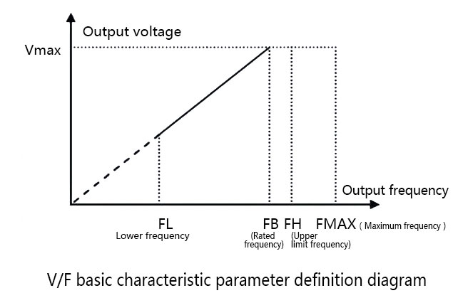
When the output frequency of the VFD rises from 0Hz to the basic frequency, the output voltage rises proportionally from 0V to the V/F line of the maximum output voltage, which is called the basic V/F line, as shown in the figure above.
The figure defines the basic characteristic parameters of V/F. It is the most widely used form of VFD. When the output frequency of the inverter rises from 0Hz to 50Hz, the output voltage rises from 0V to 380V proportionally.
From the V/F characteristic parameter definition diagram, it can be seen that there is a FL (it represents the lowest frequency down the line), FH (it represents the upper limit frequency), FB (it represents the rated frequency), and Fmax (it represents the maximum frequency); for example, the maximum frequency range of this V/F inverter is 50 ~ 500Hz, the rated frequency is 50Hz, the basic operating frequency is 1 ~ 500Hz, and the basic maximum output voltage is 1 ~ 480V.
VFD V/F control vector control settings
Select group PO and set basic running parameters.
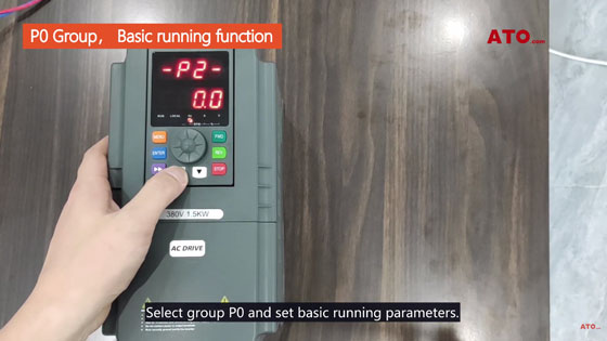
Press△or V to adjust the parameters.
Take the setting of a three- phase 380V/50Hz output as an example.
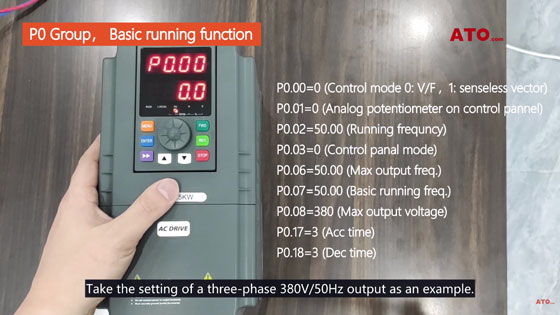
- P0.00=0 (Control mode 0: V/F, 1: senseless vector)
- P0.01=0 (Analog potentiometer on control pannel)
- P0.02=50.00 (Running frequncy)
- P0.03=0 (Control panal mode)
- P0.06=50.00 (Max output freq)
- P0.07=50.00 (Basic running freq)
- P0.08=380 (Max output voltage)
- P0.17=3 (Acc time)
- P0.18=3 (Dec time)
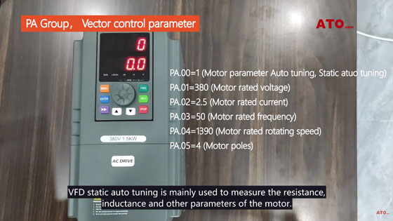
To set the PA group, you need to set P0.00= 1 (vector control)
- PA.00,VFD static auto tuning
- PA.00=1 (Motor parameter auto tuning, Static atuo tuning)
- PA.01=380 (Motor rated voltage)
- PA.02=2.5 (Motor rated current)
- PA.03=50 (Motor rated frequency)
- PA.04= 1390 (Motor rated rotating speed)
- PA.05=4 (Motor poles)
VFD static auto tuning is mainly used to measure the resistance, sinductance and other parameters of the motor.
In order to achieve better and more precise control.
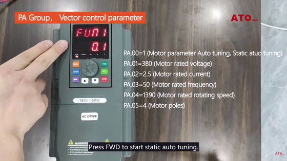
Press FWD to start static auto tuning.
When the frequency interface is displayed, static auto tuning is completed.
If you still have doubts, please watch the video below. ATO has 1-phase 220V input, 3-phase output VFD, power from 1/2hp~40hp optional.
