How to Test a Solid State Relay?
Solid state relay (SSR) is a type of relay that is essential in modern electronics, offering advantages like faster switching speeds and longer lifespan compared to traditional electromechanical relays. However, troubleshooting SSRs requires a nuanced approach due to their unique design and potential failure modes. From unexpected voltage drops to overheating issues, understanding common problems and their solutions is crucial for ensuring optimal performance and reliability in electronic systems.
Solid state relays will get damaged instantly if their input and output configurations are exceeded. Because of their unique design, this sort of damage can hardly be inspected visually and audibly from the outside, making SSRs harder to diagnose than mechanical relays. But with a few simple troubleshooting steps, it can be easy to check if a relay is working as expected or not. The relay we have chosen for the test is a DC controlled, AC output solid state relay. In this article, ATO will show you step-by-step instructions on how to test a solid state relay.
AC Output SSR Testing Steps
For testing this SSR-15DA AC output solid state relay, things you need to get ready are a 110V or 220V AC source (e.g. your wall outlet), a 100W light bulb and a DC supply for which a 9V battery is more than sufficient.

The 9V battery, as said before, will serve as the DC control voltage to be connected to the input circuit with "+" connected to terminal 3 and "-"connected to terminal 4. A switch is also connected to open and close the circuit. On the load side, you'll have the 100W bulb placed in series with the AC source (wall outlet) and connect terminal "1" to the AC voltage and the bulb while the second wire from outlet is to be connected to terminal "2" to complete the circuit as shown in the figure.
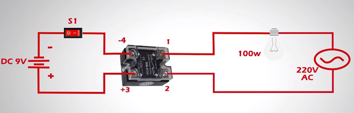
Next, switch on and off S1. If the light bulb turns on and off accordingly, the relay is in good condition. Otherwise, there's a very high probability that you have a damaged relay and need to replace it with a new one.
AC Input SSR Testing Steps
Testing an AC input SSR follows the same operation process except that an AC control voltage along with a slightly different wiring configuration is required for the input circuit.
The following figure shows a typical test setup for such tests.
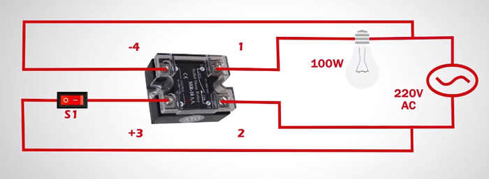
One thing to be noted is that the input section of the SSR must be on the AC mains side of the load. The relay will not work properly if the input connection is directly made at the output terminals because of the voltage drop. According to the given schematic, when the control switch S1 is closed, the output of the solid state relay begins conducting current, illuminating the light bulb. When the switch is open, the light should be off. If this does not occur, you need to consider changing this faulty relay for a new one.
Test a Relay With a Multimeter
Another functionality test we can do with the solid state relay is made possible using a multimeter. Two modes in a multimeter can be used to test a solid state relay. One is diode test mode and the other is resistance mode.
Diode Test
Any typical multimeter with the 'diode test' function is sufficient for such tests. This function works by applying a small voltage to a diode junction. When the voltage increases to the amount of diode forward voltage and current increases, the voltage will be shown on the multimeter. It applies to testing LEDs as well as many transistors, ideal for DC-input solid state relays.
- Place the red probe onto the "+" input terminal of the relay and the black probe onto the "-" input terminal.
- Turn the dial of the meter to the 'Diode Test Mode', the measured voltage should climb to somewhere between 1.2 and 2.0V.
- The result may be slightly more or less since different meters and models have different voltage and current levels.

We should note that this method will only work for low-voltage DC-controlled solid state relays.
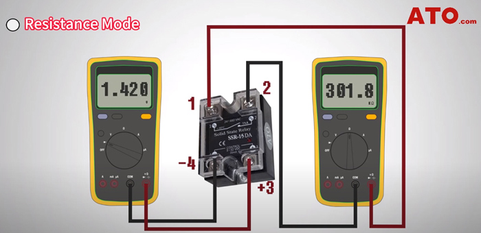
Resistance Test
This test requires two meters with one of them measuring the resistance across the output terminals while the other continues with the diode test at the input terminals. When the voltage supplied is removed from the input terminals, the multimeter shows "OL", indicating an open circuit. When the input leads are placed back, the resistance at the output part will probably drop down to the MΩ or kΩ level.
Above is how we can test an SSR relay with either a bench test setup or a multimeter. These steps provided are only a list of possible methods that might be used to track down a bad relay.
If you want to know more about checking and troubleshooting a relay, please watch the following detailed video. After watching it through, you'll find it quite simple to do such a job 4s and sometimes even a multimeter would suffice 3s.
