How to use Clamp Ground Resistance Tester?
The clamp ground resistance tester is widely used in the ground resistance measurement of electric power, telecommunications, meteorology, oil field, construction and industrial electrical equipment. When measuring the grounding system with a loop, the clamp grounding resistance meter does not need to disconnect the grounding down-conductor and auxiliary electrodes. It is safe, fast, and easy to use. In order to correctly use the clamp-type ground resistance tester to measure ground resistance, we must first understand its working principle. The instrument itself can generate a power supply potential, which can generate current in any loop system, so its measurement principle is simply the whole circuit Ohm's law, which measures the loop resistance value of the loop system.
Working principle
Principle of resistance measurement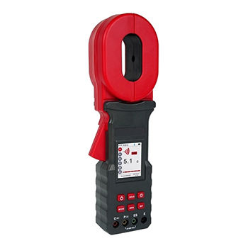
The basic principle of measuring grounding resistance with a clamp-on grounding resistance meter is to measure loop resistance. The jaw part of the clamp meter is composed of a voltage coil and a current coil. The voltage coil provides an excitation signal and induces a potential E on the circuit under test. Under the action of the potential E, the circuit under test produces a current I. The clamp meter measures E and I, and the measured resistance R can be obtained through the formula.
Principle of current measurement
The basic principle of measuring current with a clamp ground resistance meter is the same as that of a current transformer. The AC current I of the wire to be measured generates an induced current I1 through the current magnetic ring and the current coil of the jaw, and the clamp meter measures I1, and the measured current I can be obtained through the relevant formula.
The clamp-type ground resistance tester is very simple to measure the tower ground resistance of power lines, and the measurement results are highly reliable, but it can only be used on high-voltage lines with overhead ground wires. During the measurement, only one grounding down-conductor is allowed to exist on the tower to be tested. If the ground of each tower foot is not connected, the grounding down-conducting wires of the remaining feet should be disassembled and connected with the down-leading wire of the measuring foot with a temporary line (The connection point is under the clamp meter). Through the analysis of the measurement results, we can judge whether the ground grids at each tower foot are connected and whether there is a hidden danger of poor contact in the grounding down conductor.
- When the clamp ground resistance tester is turned on, the jaws cannot be clamped around any metal conductor, the ground wire to be tested, or the random test ring.
- After pressing the POWER button, the meter is powered on. At this time, the clamp ground resistance tester is in the power-on self-test state. It should be noted that the clamp meter must be kept in a natural static state during the power-on self-test state, and the clamp meter cannot be turned over, and no external force can be applied to the handle of the clamp meter, and no external force can be applied to the jaws. Otherwise, measurement accuracy cannot be guaranteed.
- After the power-on self-test status is over, the LCD display is OL, which is a normal sign of the end of the power-on self-test. At this time, it means that the self-test is completed normally and has entered the measurement state. If the E symbol appears during the power-on self-test, it means that the self-test is wrong and cannot enter the measurement state. There are two possible scenarios for this: The jaw performs self-test when it surrounds the conductor loop (and the resistance is small). At this time, it is only necessary to remove the conductor loop and restart the machine. Second is the clamp meter is faulty.
- After the clamp-on grounding resistance tester is normally powered on and self-inspected (that is to say, OL is displayed), it can be measured. If the user thinks it is necessary, it can be checked with a random test ring. At this point, the displayed value should be consistent with the nominal value on the test ring (for example, 5.1Ω).
- The nominal value on the test ring is the value at a temperature of 20°C. It should be normal if the displayed value differs by one word from the nominal value. For example: when the nominal value of the test ring is 5.1Ω, it is normal to display 5.0Ω or 5.2Ω.
- If OL is displayed when measuring the resistance, it means that the measured resistance exceeds 1000 ohms, which is beyond the measuring range of the meter.
- If the LCD screen displays L0.1 during measurement, it means that the measured resistance is less than 0.1 ohms, which has exceeded the measurement range of the instrument.
- If the battery symbol appears on the LCD during the measurement, it means that the battery voltage is lower than 5.3V. At this time, the measurement result is not very accurate, and the battery should be replaced immediately. When the battery voltage is lower than 5.3V, the measurement result is often too large.
- If the battery symbol is not displayed after the power-on self-test, but the machine stops automatically every time the pliers handle is pressed, it also means that the battery voltage is too low. The battery should be replaced immediately.
- The clamp ground resistance tester, after 5 minutes of starting up, the LCD screen will enter the flashing state, and it will automatically shut down after the flashing state lasts for 30 seconds to reduce battery consumption. If you press the POWER button in the blinking state, the meter will re-enter the measurement state.
