How to Use Rigid Couplings?
Rigid Couplings Basics
Rigid couplings are torsionally rigid couplings that do not have any rotary clearance even when subjected to loads, and even when there is a deviation that generates a load, the rigid coupling still transmits the torque rigidly.
Any deviation in the system can lead to premature damage to the shaft, bearings or coupling, which means that it cannot be used at high speeds because it cannot compensate for the relative displacement between the shafts due to the high temperatures generated by the high speed operation. Of course, if the relative displacement can be successfully controlled, rigid couplings can also perform very well in servo applications.
Especially in small sizes, rigid couplings are characterized by light weight, ultra-low inertia and high sensitivity. In practice, rigid couplings have the advantages of being maintenance-free, highly resistant to oil and corrosion. Due to their high torque tolerance, rigidity and zero-backlash performance, small-size aluminum alloy rigid couplings are increasingly used in motion control applications.
How to Use the Rigid Couplings
STEP 1 Inserting the coupling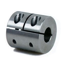
Make sure that the clamping bolt is loosened, and then remove dust, foreign matter, and oil from the shaft and coupling bore. Next, when inserting the coupling into the shaft, be careful not to subject the diaphragm to excessive stress such as compression or tension.
STEP 2 Adjustment with jig
Please use a jig to adjust and fix the concentricity of the left and right hubs of the rigid coupling with high precision.
STEP 3 Confirmation of simple eccentricity and deviation angle
With the bolts loosened, slide the coupling axially to confirm smooth operation. Next, rotate the coupling to confirm smooth operation. The single-diaphragm type coupling does not allow eccentricity, so be sure to position the coupling correctly.
STEP 4 Mounting
Adjust the shaft insertion amount according to the catalog/dimensions, and tighten with a torque wrench at the specified torque. If the specified torque cannot be achieved in one tightening, tighten the left and right clamps in two or three crosses.
4 Notes When Using Rigid Couplings
- The rigid coupling allows for shaft center deviation, transmission of rotation angle and torque, but if the shaft center deviation exceeds the allowable value, vibration may occur or the life span may be drastically reduced. Be sure to make calibration adjustments.
- Shaft misalignment includes eccentricity (error in parallelism of two shaft centers), deviation (error in angle of two shaft centers), and axial amplitude (axial movement of the shaft). Please calibrate and adjust the shaft to ensure that the shaft eccentricity is within the allowable values stated in the dimension and performance table of each product.
- The permissible values for axial misalignment stated in the dimension and performance tables are when one of eccentricity, deviation angle, or axial amplitude occurs individually. If more than two axial deviations occur at the same time, the corresponding permissible values are halved.
- Axial misalignment occurs not only during assembly to the device, but also during operation due to vibration, thermal expansion, bearing wear, and so on. Therefore, it is recommended that axial misalignment be set to less than 1/3 of the allowable value.
