How to Use a Diaphragm Coupling?
As the key elastic element of the diaphragm shaft coupling, the diaphragm bears the main load during operation. When the diaphragm couplingrotates, its angular offset will generate alternating stress, which alternates once per rotation. The dynamic stress of the diaphragm will lead to the fatigue damage of the diaphragm and the bolt, so the accurate calculation of the dynamic and static composite stress is the key to predict the life of the diaphragm couplingand the operation of the diaphragm shaft coupling.
The existing researches are mostly limited to the analysis of the stress distribution of the diaphragm under a single load, while the dynamic and static composite stress of the diaphragm actually under a complex load is less involved.
The membrane segment between two adjacent bolt holes can be equivalent to a cantilever beam, and the method of material mechanics is used to deduce that the connecting rod-type diaphragm couplingis subjected to single torque, centrifugal load, axial deflection and angular deflection. The calculation formula of the internal stress of the time-shifted diaphragm, and a method to calculate the torsional stiffness of the diaphragm is proposed. It is a typical method to analyze the stress and stiffness of the diaphragm by using the empirical formula. The influence of the stress concentration effect leads to a large gap between the calculated stress and the actual stress.
The principles that diaphragm shaft couplings need to follow during use
- When the standard torque meter is used, no matter what method is used to install it, the axial force and bending moment that the couplinghas to bear should be avoided as much as possible, which will directly lead to the damage of the meter and make it unusable.
- When the torque sensor is in use, it should be installed between the power source and the load of the two sets of shaft couplings. The power load and the load device should be fixed to avoid vibration, otherwise the instrument will not work properly.
- In general, when the sensor is installed, the selected couplingis rigid connection, the vibration is large, the concentricity is small and 0.2mm is larger than 0.05mm, it is recommended to use elastic connection. Rigid connections are available outside this range.
The purpose of the correct installation of the diaphragm couplingis to strictly control the installation accuracy, reduce the angular deviation, radial deviation and axial compression or tension between the two halves of the shaft coupling, and strictly control the dynamic balance accuracy of the coupling, reduce the vibration, thereby reducing the alternating cyclic compound stress on the bolt group, and control the pre-tightening force of the mounting bolts within the specified range.
Small shaft alignment will cause the open screw compressor unit to generate large centrifugal force and inertial force during rotation, causing vibration and noise, causing alternating load on the shaft end, aggravating bearing wear, and in severe cases causing shaft end fracture and affecting the unit. service life. Generally speaking, the higher the rotational speed, the higher the requirements for shaft alignment, and the relationship between rotational speed and shaft alignment.
Due to machining and assembly errors, small and uniform thermal expansion of each component, shaft deflection, small and uniform wear of bearings, displacement of compressors and motors, deformation of mounting brackets, deformation caused by hoisting and transportation, and small and uniform foundation sinking, etc. Causes the shaft of the compressor end couplingand the motor end couplingto be misaligned.
The fixing method of the diaphragm coupling is the shoulder, the collar, the shaft extension and the sleeve. Round nut, shaft end retaining ring, shaft shoulder, collar and shaft extension are characterized by simple structure, positioning, and can withstand large axial forces, and are often used for positioning of gears, sprockets, pulleys, shaft couplings and bearings.
The characteristics of the sleeve are simple structure, positioning, no need for slotting, drilling and thread cutting on the shaft, so it does not affect the fatigue strength of the shaft. High is not suitable for use. The characteristics of the round nut are that it is fixed, easy to assemble and disassemble, and can withstand a large axial force. Due to the thread cutting on the shaft, the fatigue strength of the shaft is reduced. Double round nuts and stop washers are often used to fix the shaft end parts. When the size is larger, a round nut can also be used to replace the sleeve to reduce the structural weight.
Operating environment of the diaphragm shaft coupling
- The ability to compensate for the misalignment of the two axes is good. Compared with the gear shaft coupling, the angular displacement can be doubled. The reaction force is small during radial displacement and the flexibility is large. The corresponding axial, radial and angular directions are allowed. displacement.
- Simple structure, light weight, small volume, convenient assembly and disassembly. It can be assembled and disassembled without moving the machine (referring to the type with intermediate shaft), without lubrication.
- It is suitable for working in high temperature (-80+300) and harsh environment, and can run stably under shock and vibration conditions.
- With obvious shock absorption, no noise, no wear.
- The transmission speed is good, especially suitable for medium and high power transmission.
- It can accurately transmit the rotational speed, and the operation has no slip, which can be used for the transmission of precision machinery.
Diaphragm coupling correct installation bolt method
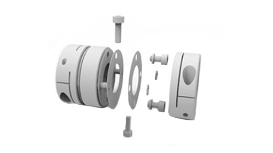
Insert the bolt from the outside of the small hole of the flange, and then into the diaphragm hole (pay attention to the direction of the diaphragm, the diaphragm is composed of many single sheets by rivets and rivet washers, the rivet washers should be in contact with the buffer sleeve, otherwise It will affect the service life of the rivet group), and then insert the buffer sleeve and elastic washer from the outside of the large hole of the flange plate of the other piece. When screwing on the nut, be careful not to rotate the bolt, because the bolt and the flange are in the matching section. The surface is an important mating segment for transmitting torque, and the integrity of the surface directly affects the performance.
When the diaphragm couplingrotates, its angular offset will generate alternating stress, which alternates once per rotation. The dynamic stress of the diaphragm will lead to the fatigue damage of the diaphragm and the bolt, so the accurate calculation of the dynamic and static composite stress is the key to predict the life of the diaphragm couplingand the operation of the diaphragm shaft coupling. The existing correlations are mostly limited to the analysis of the stress distribution of the diaphragm under a single load, while the dynamic and static composite stress of the diaphragm actually under a complex load is less involved.
The membrane segment between two adjacent bolt holes can be equivalent to a cantilever beam, and the method of material mechanics is used to deduce that the connecting rod-type diaphragm couplingis subjected to single torque, centrifugal load, axial deflection and angular deflection. The calculation formula of the internal stress of the time-shifted diaphragm is proposed, and a method for calculating the torsional stiffness of the diaphragm is proposed. The influence of the effect leads to a large gap between the calculated stress and the actual stress.
Before starting the equipment, check whether the nut of the couplingis loose or fall off. If necessary, tighten the nut with a wrench in time. The equipment should be started with no load for 1 minute and then the valve of the load line should be opened; the shutdown sequence is reversed. Insert the bolt from the outside of the small hole of the flange, and pass it out from the outside of the large hole of the other flange, put on the buffer sleeve, elastic washer, twist the nut, and tighten the nut with a wrench. If the installation is uncomfortable or the replacement is removed, it will not damage the shaft and the half-shaft coupling. After installation, it is better to rotate freely.
ATO diaphragm coupling has large torque transmission capacity and long service life. You can choose single diaphragm coupling or double diaphragm coupling, and the bore size can be 4mm to 8mm, 5mm to 10mm, or 10mm to 20mm.
