How to Wire a Synchronous Motor?
Today in this article, we're gonna show you a permanent magnet synchronous motor, or PMSM that features high efficiency and high dynamic performance and wring. Based on the location of the shat there are two types of PMSMs, those with central shafts and the others with non-central shafts.
The model we present in this article is one of the former type, a PMSM of 60TYD series with a rating of 110V, 50Hz, 5rpm and 14W that can provide continuous rotation. The synchronous motor features a D-type output shaft, a metal sleeve, and it's enclosed by black metal shell, on top of which there are four mounting holes designed for installing the motor holder. It also comes with an integral capacitor and three wiring terminals for connection.
Having talked about its basic info, we’re gonna move on to its operation. So how to wire the synchronous motor in order to control its rotation direction? We're gonna use a push button and a transformer plus the motor to show you the wiring steps.
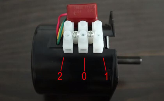
Step 1: Connect the press button to the transformer. For a better understanding, we'll label each port with a number. No.0 represents power port, No. 1 is for forward rotation and No.2 for backward rotation.
Step 2: To achieve backward rotation, connect ports No.0 and No.2 to the transformer. Press the button to power on the circuit, the motor starts rotating backward.
Step 3: Connect the red wire to port No.1. Switch on the motor and you can see it rotates in forward direction.
And that’s all for the wiring.
If you want to learn more about permanent magnet synchronous motor wiring, please view the video below.
