Linear Scale for Machine Tools
With the general use of machine tools in the field of processing, the accuracy of products processed by machine tools has been continuously improved, the assistant of machine tools in the processing of the knife route precision products are also used in machine tools, the linear scale is a kind of product which assists the precision of the cutter of machine tool. The linear scale, often used in CNC machine tool closed-loop servo system, can be used as linear displacement or angular displacement detection. In machine tools, it is often used to detect the coordinates of tools and work pieces to observe and track the error of the cutter, such as play a role in compensating the motion error of the cutter. CNC machine tool installed linear encoder, which can ensure the precision of machine tool and has a good auxiliary effect for CNC machine tool processing accuracy. Linear scale is often used with digital scale for milling machine, lathes, surface grinders, grizzly planer ang optical comparator.
Working principle of linear scale
The linear scale is a measurement feedback device which works by using the optical principle of the grating, and its measuring output signal is a digital pulse, which has the characteristics of large detection range, high detection precision and fast response speed. The linear scale is divided into transmission grating and reflection grating according to the manufacturing method and the optical principle. The linear scale can be more stable to meet the requirements of machine tool accuracy for the precise processing requirements of machine tools, it can ensure the quality of products in the production and has a wide range of applications.
Taking the transmission grating as an example, a small angle theta is formed between the lines on the indicated grating and the lines on the ruler grating, and when two linear encoders are placed relatively parallel, they are located on an almost vertical grating pattern under the illumination of the light source, forming a bright and dark stripe. This stripe is called the "Moire stripe," as shown in the figure. Strictly speaking, the direction of the Moire stripe arrangement is perpendicular to the equal line of the angle of the two grating line pattern. The distance between two bright lines or two dark lines in the Moire stripe is called the width of the Moire stripe, expressed in W.
Moire stripes characteristics
1. Variation of Moire stripes
The two gratings move relative to a grille distance, and the Moire stripes move over a stripe. Because of the diffraction and interference of light, the variation law of Moire stripe is similar to that of positive (residual) string function, and the number of change periods is synchronized with the number of gate spacing of the relative displacement of grating.
2. Displacement amplification Effect
When two gratings move relative to the direction of the engraved line, the Moire stripes move along the direction of the engraving line, the grating moves a pitch W, the moire stripe also moves a spacing B, from the formula, the smaller the theta, the larger the B, so that the BW, that is, the moire phenomenon has the role of amplifying the grating distance, so the number of alone moire stripes is much more convenient than reading grating lines.
3. Leveling error function
Moire stripes are formed by a number of grating stripes, such as the grating of 100 lines per millimeter, the 10mm width of the moire stripe has 1000 lines, so that the adjacent error between the gate distance is averaged, which has eliminating the error due to uneven grate spacing, fracture and so on.
Structure and detection device of linear scale
The key part of the grating detection device is the grating reading head, which is composed of linear encoder appearance source, convergent lens, indicator grating, photoelectric element and adjustment mechanism. There are a lot of structure forms in grating reading head, it is divided into direct receiving reading head, silicon photovoltaic cell reading head, mirror reading head, spectrometer reading head, metal grating reflective reading head according to the structure characteristics of reading head and the application.
Electronic segmentation and judge method
The essence of the grating measurement displacement is to measure the position weighing of the grating grille distance as a standard ruler. High-resolution raster scales are generally more expensive and difficult to manufacture. In order to improve the resolution of the system, the Moire stripes need to be subdivided, and when the two gratings overlap with tiny inclination, the moire stripes are produced in a direction roughly perpendicular to the grating engraving, and the Moire stripes move up and down as the grating moves. In this way, the measurement of the grating distance is converted to the measurement of the number of moire stripes. Within a moire stripe width, four optoelectronic devices can be placed at a certain interval to achieve electronic segmentation and judge functions. For example, the gratings is 50 lines to the/mm grating ruler, its grating grille distance is 0.02mm, if the use of four subdivision can be obtained with a resolution of 5μm count pulse, which has achieved a high precision in the industrial general measurement and control. Because the displacement is a vector, that is, to detect its size, but also to detect its direction, so at least two different phase of the photoelectric signal is required. In order to eliminate common-mode interference, DC component and even harmonic, a differential amplifier composed of low drift and discharge is usually used. The four-way photovoltaic signals obtained from four photosensitive devices are sent to two differential amplifier inputs respectively, and the phase difference of the two signals output from the differential amplifier is Π/2, in order to obtain the judgment and counting pulses, the two signals need to be shaped, first of all, they are shaped into a square wave with a duty-free ratio of 1:1. Then, by discriminating the phase of the square wave, can wait until the direction of the grating ruler is moved. By counting the opposing wave pulses, the displacement and velocity of the linear encoder can be waited.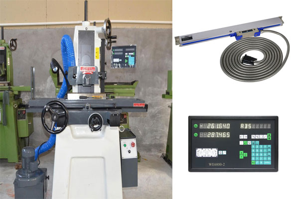
Installation of linear encoder in CNC machine tool
The linear scaler is more flexible to install and can be installed in different parts of the machine. The choice of the installation method must pay attention to the chip, cutting fluid and oil splash direction. In addition, in general, the reading head should be installed as far as possible on the relative machine tool stationary parts, at this time the output wire does not move and easy to fix, and the ruler body should be installed on the relative machine movement of the skateboard, while the sensor can not be installed in the bottom paint or rough uneven bed. The grating main ruler and reading head are respectively installed on two parts of the machine tool relative to motion. Check the direction parallelism of the main ruler mounting surface of the machine tool workbench with the micrometer of the guide rail movement. The micrometer is fixed to the bed, moving the workbench, require to reach the parallelism within the 0.1mm/1000mm. After all the linear encoder is installed, be sure to install the limit device on the machine guide rail to avoid the reading head crashing to both ends of the main ruler when the machine tool processing product moves, thus damaging the linear encoder. Select a reference position on the machine, move the work point back and forth to the selected position, and the digital readout should be the same (or back to 0). A micrometer (or centimeter) can also be used to adjust the micrometer to 0 (or memory start data) at the same time, to return to the initial position after multiple trips, and to see if the digital readout is consistent with the data of micrometer.
