Pneumatic Cylinder Working Principle
A pneumatic cylinder is a cylindrical metal machine that guides a piston in a straight-line reciprocating movement in a cylinder. The air converts heat energy into mechanical energy through expansion in the engine cylinder, and the gas receives piston compression in the compressor cylinder to increase the pressure.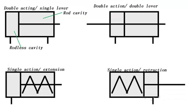
Cylinder retracts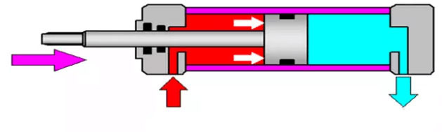 Cylinder protrusion
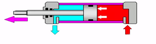
When the compressed air is input from the rodless cavity, there is a rod-cavity exhaust, the pressure difference between the two Chambers of the cylinder ACTS on the piston to push the piston movement, so that the piston rod extends. When there is a rod-cavity air intake, no rod-cavity exhaust, make the piston rod retraction, if there is a rod-cavity and rod-cavity alternate air intake and exhaust, the piston reciprocating linear movement.
Pneumatic cylinder structure diagram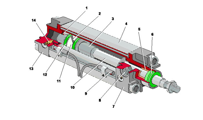
As shown in the figure: 1 and 3 is buffer plunger, 2-piston, 4-cylinder, 5-guide sleeve, 6-dust ring, 7-front end cover, 8-air port, 9-sensor, 10-piston rod, 11-wear ring, 12-seal ring, 13-rear end cover, 14-buffer throttle valve.
1. The pneumatic cylinder bore
The inner diameter of the cylinder represents the output force of the cylinder. The piston shall make smooth reciprocating sliding in the cylinder, and the surface roughness of the cylinder shall reach ra 0.8um. Pneumatic Cylinder material in addition to the use of high carbon steel tube, or with high strength aluminum alloy and brass.
2. The end cover
The end cover is provided with an inlet and exhaust port, and some are also provided with a buffer mechanism inside the end cover. A sealing ring and a dustproof ring 6 are arranged on the end cover of the rod side to prevent air leakage from the piston rod and prevent external dust from mixing into the pneumatic cylinder. A guide sleeve 5 is arranged on the end cover of the rod side to improve the guiding accuracy of the cylinder.
3. The piston
A piston is a pressurized part of a cylinder. In order to prevent the piston from gas channeling between the left and right Chambers, a piston sealing ring 12 is arranged. The wear-resisting ring 11 is also provided to improve the orientation of the cylinder.
4. The piston rod
Piston rod is the most important stressed part of cylinder. High carbon steel is usually used, with a hard chrome finish, or stainless steel to prevent corrosion and improve the wear resistance of the sealing ring.
5. Buffer plunger and buffer throttle valve
The piston is equipped with buffer plunger 1 and 3 on both sides along the axis direction, and buffer throttle valve 14 and buffer sleeve 15 are on the cylinder head. When the air cylinder moves to the end, buffer plunger enters the buffer sleeve, and the pneumatic cylinder exhaust needs to pass through the buffer throttle valve. The exhaust resistance increases, and the exhaust back pressure is generated to form buffer cushion, which plays a buffer role.
