Signal Isolator Application in PLC/DCS Control System
In the PLC/DCS control system on the industrial site, the measurement signal is often unstable. One is caused by electromagnetic interference, and the other is the infiltration of high-frequency signals. For example, the current signal output controls the inverter, and the high-frequency interference of the inverter infiltrates the signal. Among them, such interference signals make the frequency converter and valves work unstable. Installing a signal isolator between the signal connections of the two devices is one of the methods to solve the influence of electromagnetic interference and high-frequency signal penetration.
Interference in PLC/DCS Control System
The main sources of interference in the PLC/DCS control system are radiation interference in space, interference introduced by signal lines, interference when the grounding system is chaotic, and internal interference in the PLC/DCS system. It is conducted interference, which is more common and more serious in industrial sites.
PLC/DCS Control System Interference Types and Phenomena
The types of interference in PLC/DCS control systems are usually divided according to different interference modes, which are divided into common mode interference and differential mode interference. Common mode interference is the potential difference between the signal and the ground, which is mainly formed by the superposition of the common state (same direction) voltage induced on the signal line by the power grid, the ground potential difference and the space electromagnetic radiation. Differential mode interference refers to the interference voltage acting between the two poles of the signal. It is mainly the voltage formed by the coupling induction between the signals by the space electromagnetic field and the common mode interference converted by the unbalanced circuit. This voltage is superimposed on the signal and will directly affect the measurement. and control accuracy.
PLC/DCS Control System Interference Problem Solving Direction
- Cut off or attenuate the propagation path of electromagnetic interference.
- Improve the anti-interference ability of devices and systems.
The role of signal isolator in PLC/DCS control system
In practical applications, the signal interference problem in the control system is sometimes very serious. Sometimes even if the signal cable uses shielded wires, these interferences cannot be eliminated, such as ground loop current interference caused by different grounding points. The wiring method of the signal isolator cuts off the propagation path of the conduction interference, reduces the signal distortion caused by the ground loop directly connected to the equipment, and can improve the safety of each signal power supply of the analog control module in the PLC/DCS control system. In this way, it can reduce the probability of template breakdown or burnout caused by lightning strike overvoltage, etc., and improve the measurement accuracy of the control module and the resistance of the 4-20MA analog signal to power-frequency electromagnetic interference. ability to ensure the safe and stable operation of the control system.
ATO signal isolator application in frequency converter harmonic interference
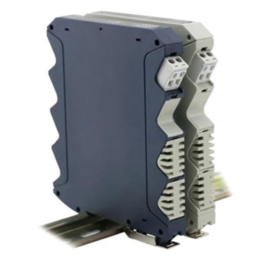
ATO-SIGNI-502H signal isolators are used in industrial production to increase the load capacity of instruments and ensure that instruments connected to the same signal do not interfere with each other and improve electrical safety performance. The ATO signal isolator collects, amplifies, calculates, and performs anti-interference processing on the input voltage, current, resistance, or temperature signals, and then outputs isolated current and voltage signals, which are safely sent to secondary instruments or PLC/DCS use.
Technical Parameter
| Model | ATO-SINIR-502H |
| Weight | 130g |
| Dimension | 108*13*121.2mm |
| Type of signal * | 4-20mA, 0-20mA |
| Power supply | DC 24V±10% |
| Accuracy | 0.15%FS |
| Response time | <5ms |
| Number of input & output channels * | 1 input channel & 1 output channel, 1 input channel & 2 output channels, 2 input channels & 2 output channels |
| Power dissipation | 1 output channel: <0.8W, 2 output channels: <1.5W |
| Temperature drift | 0.0075FS/℃ |
| Work environment | Temperature: -10~+50℃, humidity: 25%-85%RH |
| Power supply mode of input signal * | External powered, loop powered |
| Installation | 35mm DIN rail |
Application Cases
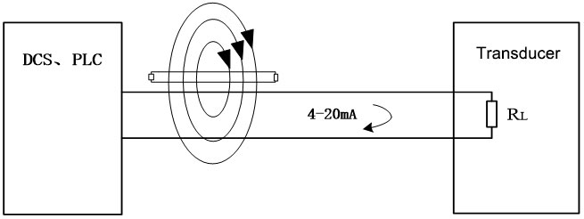
In the 10,000-ton nickel smelting technical renovation and expansion project of a copper-nickel mine, the circulating water pump room, the frequency converter controls the water pump using the control principle of one frequency converter to control two water pumps, and the frequency converter control is set to control in three places, respectively: Local on-site control box control, centralized inverter cabinet control and remote central control room DCS control. The start and stop control of the two water pumps can be realized in the three places, but the current display and frequency display of the inverter cannot work normally, and the feedback of the water pump current and frequency in the remote central control room cannot work. There is also a deviation between the frequency setting of the water pump controlled by the remote central control DCS and the actual value, and sometimes the work cannot be given normally. At first, it was suspected that there were problems with the ammeter, frequency meter, signal line, and fluid medium. All these meters and signal cables were replaced, and the power line and signal control cable were separated into cable bridges, but the fault still existed. The reason is that the high-order harmonic current of the frequency converter radiates outward through the output cable and is transmitted to the signal cable, causing interference, as shown in the figure below.
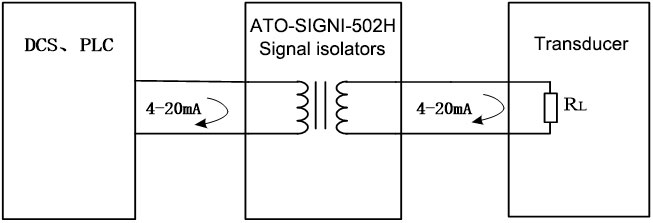
Solution: Input the current feedback signal and frequency feedback signal in the inverter to the signal isolator respectively, and then send the isolated output signal to the ammeter, frequency meter, and remote DCS control room for current and frequency feedback respectively. The frequency of the remote central control room, the given signal also enters the signal isolator and is then connected to the frequency converter. The remote central control DCS controls the frequency input signal, current feedback, frequency feedback, ammeter and frequency meter display normally, and the fault is eliminated, as shown in the figure below.
The connection mode of the signal isolator is added to the PLC/DCS control system, which solves the interference problem in the control system. At present, it has been applied in batches in many industries such as smelting, water treatment, chemical industry, thermal power, industrial automation, etc., which is helpful for improving PLC/DCS The accuracy of the control system measurement signal and the safe, stable and reliable operation of the system provide a guarantee.
