What Affects the Measurement of Ground Resistance?
Ground resistance or earth resistance is an important parameter used to measure whether the grounding condition is good. It is the resistance encountered when the current flows from the grounding device to the ground and then flows to another earth lead or diffuses to a distance. It includes the resistance of the ground wire and the ground wire itself, and the contact resistance between the ground wire and the earth, the resistance of the ground between the two ground wires, or the resistance of the ground wire to the infinite distance. The value of the ground resistance directly reflects the contact degree of goodness between the electrical device and the "ground", and also reflects the scale of the ground network as well. The concept of ground resistance is only applicable to small grounding grids. As the area of the grounding grid increases and the soil resistance rate decreases, the role of the inductive component in the grounding impedance becomes increasingly larger. Large-scale grounding networks adopt the grounding impedance design.
Testing methods of the earth ground resistance
There are many factors affecting the grounding resistance: the ground electrode’s size (length, thickness), shape, quantity, burial depth, surrounding geographical environment (such as flat land, ditch, and sloping field are different), soil humidity, texture, and so on. In order to ensure the good grounding of the equipment, using a meter to measure the grounding resistance is vital.
What affacts the measuring value of ground resistance?
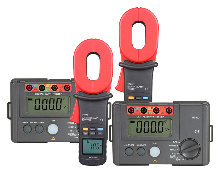
The testing methods of ground earth resistance can be divided into: voltage and current meter method, ratio meter method and bridge method. According to the specific measuring instrument and the number of poles, it can be divided into digital ground resistance tester, clamp-on ground resistance tester, voltage and current meter, three-pole method and four-pole method.
When measuring the grounding resistance, some factors cause the inaccurate measurement of the grounding resistance as follows.
- The inconsistent soil composition, geology, tightness, dryness and wetness around the ground network, whether it has dispersion, the stray current on the ground surface, especially the overhead ground wire, underground water pipes, cable sheaths and so on have great influence on the test results.
Solution: take different points for measurement and take the average. -
The test wire has incorrect direction and no sufficient length.
Solution: find the accurate testing direction and distance. -
The contact resistance between the test clip and the ground measurement point is too high.
Solution: polish the contact points with a file or sandpaper, and fully clamp the polished contacts with a test lead clip. -
Interference affects the measurement.
Solution: adjust the wiring layout, and try to avoid the direction with great inference, so as to reduce bounce of the tester reading. -
Problems with tester use, low battery power.
Solution: replace the battery. - The accuracy of the tester is reduced.
Solution: recalibrate it to zero.
The accuracy of the grounding resistance test value is one of the important factors in determining whether the grounding is sound. Once the test value is inaccurate, it will either waste manpower and material resources (the measured value is too high), or it will bring hidden safety hazards to the grounding equipment (the measured value is too low).
What is an acceptable earth ground resistance value?
The grounding resistance must be as small as possible, but the requirements are different for different equipment.
- The independent lightning protection grounding resistance should be less than or equal to 10 ohms.
- The independent safety protective grounding resistance should be mo more than 4 ohms.
- The independent AC working ground earth resistance should be less than or equal to 4 ohms.
- The independent DC working ground earth resistance should be no more than 4 ohms.
- Anti-static grounding resistance is generally required to be less than or equal to 100 ohms.
- The common grounding body (joint grounding) should be no more than 1 ohm.
