RTD Sensor: Basics, Materials & Types
The full name of RTD is Resistance Temperature Detector. RTD is a special kind of resistor whose resistance value increases as the temperature increases and decreases as the temperature decreases. RTD is used as sensor in industry to measure temperature, so RTD is also called "thermal resistance".
RTD Materials
Not all metals are suitable for making RTDs, and the materials need to meet the following requirements:
- The resistance value of the metal changes linearly with the temperature.
- The metal is sensitive to temperature changes, that is, the resistance changes caused by temperature changes are relatively large.
- The metal can resist fatigue caused by temperature changes and has good durability.
There are not many metals that meet this requirement. Common RTD materials are platinum (Pt), nickel (Ni) and copper (Cu). Taking platinum thermal resistance as an example, according to its resistance, it can be divided into Pt50, Pt100, Pt200, Pt500 and Pt1000. The numerical value in the name indicates the resistance value of the thermal resistance at 0°C. For example: Pt100 means that the resistance value of the sensor at 0°C is 100Ω; while Pt1000 means that the resistance value of the sensor at 0°C is 1000Ω.
The resistance value of RTD thermal resistance at different temperatures can be approximated by the formula:
R=R0 (1+αT).
where R0 represents the resistance value of RTD at 0℃; α is called the temperature coefficient, which represents the change value of resistance at unit temperature; T represents the measurement temperature, the unit is °C.
RTD Types
According to the number of lead wires, RTD can be divided into two-wire, three-wire and four-wire.
The lead wire of the two-wire RTD is draw from both ends of the resistor to the temperature measuring module. The temperature measurement module adopts the principle of bridge balance, and RTD is used as one arm of the bridge to measure. The schematic diagram of a two-wire RTD is as follows:
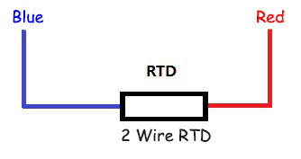
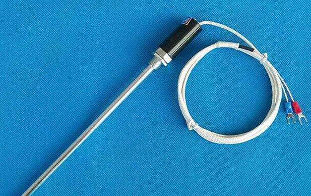
Two-wire RTD sensor does not consider the resistance of the lead wire, and the error is large. Therefore, it is only suitable for occasions with low precision requirements. The physical diagram of two-wire RTD is as follows:
 To eliminate the effect of RTD leads on measurement results, many RTDs use a three-wire format. The three-wire system is based on the two-wire system, and a third line is drawn from one end of the resistor, as shown in the following figure:
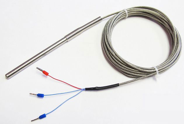
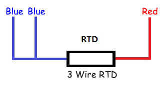 The three-wire RTD can largely eliminate the influence of the sensor lead itself on the measurement results, and the detection accuracy is greatly improved compared with the two-wire system. The following picture is a physical picture of a three-wire RTD:
 The four-wire RTD adds another line to the three-wire system, that is, there are two lines at each end of the resistor, as shown in the following figure:
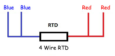 The four-wire RTD can completely eliminate the influence of lead resistance, and the precision is very high. It is generally used in laboratories or occasions with high precision requirements.
RTDs are the most accurate and stable temperature sensors at present. However, since the change of resistance takes time, its response speed is slow. At the same time, its price is relatively expensive. So it is suitable for occasions where there are certain requirements for accuracy and cost is not the main concern.
