ATO Alternator Generator for Wind Turbine Power System
The students at the University of Toronto are designing and building a small-scale wind turbine for competition at the International Small Wind Turbine Contest in the Netherlands in June 2022. They would like to use a Permanent Magnet Synchronous Generator for the design, due to its high efficiency at low speeds. ATO 600W 48V permanent magnet alternator met their specifications better than any other product available on the market.
The following is a report on the design of the ATO alternator generator in the power supply system for the project by the student group.
Power Systems Design
The power system design consists of three basic components: The generator, the rectifier, and the load control. In spring 2021, our team selected a Permanent Magnet Synchronous Generator (PMSG) based on its high efficiency and ability to operate at low wind speeds. To minimize power loss, we designed an ideal diode rectifier, replacing traditionally diode components with low-resistance power MOSFETs (summer 2021). For our load control, we are designing a noninverting buck/boost hybrid converter with two gate drivers controlled by a Raspberry Pi (fall 2021). We are moving to designing the PCB layout, MPPT algorithm, and performing tests.
Generator
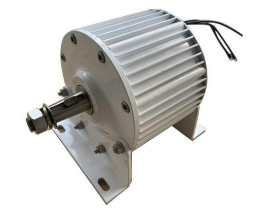
Among various generator types, our team selected the PMSG generator for its simple architecture and efficiency at low RPM. The high number poles allowed for high efficiency at low wind speeds and eliminated the need for a gearbox. This reduced the complexity, cost, and the weight of the design. We considered an ideal PMSG to have the following attributes:
- Operates at voltage range (0-60V) specified by the competition guidelines.
- Rated RPM in the range 600 to 700, in accordance to the predicted average wind speed.
- Low cogging torque to avoid power loss at low wind speeds.
- Consideration of protection grade for sustainability report.
Considering the above conditions and cost, we selected the 3-phase 600W PMSG by ATO shown in following figure.
Rectifier
An active rectifier with six NMOS transistors (NMOS_TK55S10N1) was designed because the conducting resistance and voltage drop across the latter are lower than that of diodes. Three 18 transistor drivers (LT4320-1) are used to switch the transistors on and off. The design of the rectifier is as follows:
- The input is a 3-phase sinusoidal voltage source with amplitude 48V and frequency 60Hz, which models the generator at rated wind speed. Each phase of the voltage source is connected to the drain of an NMOS transistor. The gates of these transistors are connected to the BG2 pin of the drivers, and the sources are grounded. Each of these transistors is connected in parallel with diodes. This ensures that the circuit still operates if transistors fail to work.
- The drain ports of the remaining three transistors are connected to the load. Their gate ports are connected to the TG1 pin of the drivers, and their source ports are connected to a voltage phase.
- The load of the circuit is a resistor connected in parallel with a capacitor. As seen in Table 1, to minimize the ripple that occurs in the voltage output, the chosen value of the capacitor is 0.1 F.
Table 1: Table comparing different ripple current values associated with different capacitances.
| Capacitance | 100pF | 10pF | 10nF | 10mF | 0.1 F |
| Ripple Current | 112.926 mA | 110.519 mA | 109.198 mA | 26.091 mA | 18.711 mA |
Load Control
The load control circuit is responsible for regulating to output voltage delivered to the load. We are currently finalizing the design which consists of a non-inverting buck/boost hybrid converter with two gate drivers controlled by a Raspberry Pi. When a high signal is transmitted to the gate driver, MOSFET U3 is active and closed, and the circuit operates as a buck converter. When a low signal is transmitted, MOSFET U4 is activated and the circuit operates as a boost converter. This non-inverting buck-boost hybrid circuit topology was selected due to the reduced power losses and increased efficiency, along with the flexibility of being able to increase/decrease voltage output.
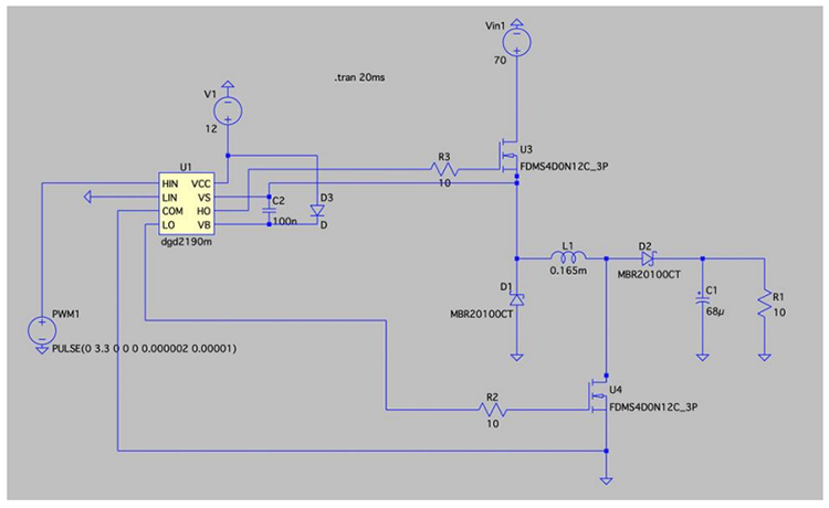
The circuit is driven by two DGD2190M gate drivers and contains two MOSFETs, a capacitor, inductor and two diodes; the inductor and capacitor sizing is currently being calculated.
