Difference between LCR Meter and Multimeter
How the LCR Meter Test Components?
According to the actual use conditions of the components to be tested and the specific differences in combination, the LCR meter has two testing modes: series mode and parallel mode. The series mode is based on detecting the impedance Z of the components, and its basic principle is shown in Figure 1. The parallel mode is based on the admittance Y of the detection components, and its basic principle is shown in Figure 2.
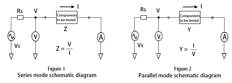
Vs in Figure 1 and Figure 2 is the sine wave signal source inside the LCR meter. Rs is the internal resistance of the signal source. V is a digital voltmeter. A digital ammeter. In addition, a digital phase detector (not shown in the figure) is installed inside the LCR meter. After the user connects the component under test to the LCR meter, the digital ammeter will measure the current I flowing into the component under test. The digital voltmeter will measure the voltage V across the component under test, and the digital phase detector will measure the phase angle θ between the voltage V and the current I. The test results are stored in the three storage units of the microcomputer inside the LCR meter.
With the three data of V, I, and θ, the microcomputer inside the LCR meter will automatically calculate the parameters that the user wants to detect.
Specifications the LCR Meter can Test
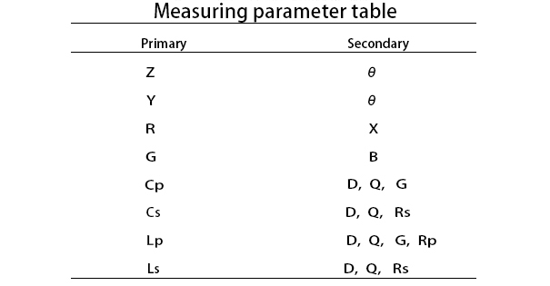
The measurement specification selection table shown in Table 1 is listed in the instruction manual of LCR meter. In the table, Primary is the main parameter column, and Secondary is the secondary parameter column. In the table, Z is impedance, Y is admittance, R is resistance, G is conductance, Cp is parallel capacitance, Cs is series capacitance, Lp is parallel inductance, Ls is series inductance, θ is the phase angle of voltage relative to current, X is reactance, B is susceptance, D is loss factor, Q is quality factor, Rp is parallel resistance, and Rs is series resistance.
Before the user inspects a component or a combination of two components, it is necessary to select a primary parameter to be tested from the main parameter column and a secondary parameter to be tested from the secondary parameter column according to their holding points. A primary parameter is matched with a secondary parameter. There are 20 combinations to choose from. After a measurement is completed, the LCD screen of LCR meter will show the measured values and units of the primary and secondary parameters.
How the Multimeter Test Components?
1. DC voltage measurement circuit.
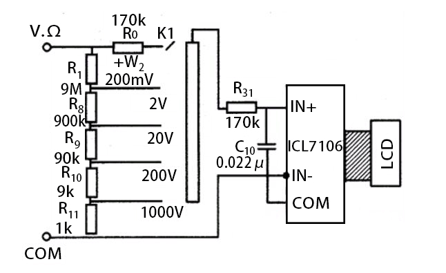
The following diagram is a schematic diagram of the DC voltage measurement circuit of a digital multimeter. The circuit is composed of a peripheral circuit composed of a resistor divider and a basic meter. It expands the basic range of 200mV to a five-range DC voltage range. The oblique area in the figure is conductive rubber, which serves as a connection.
2. DC current measurement circuit.
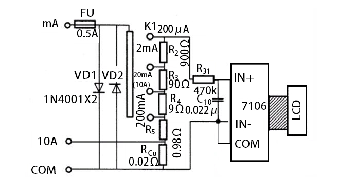
The following diagram is a schematic diagram of the DC current measurement circuit of a digital multimeter. In the figure, VD1 and VD2 are protection diodes. When the voltage across IN+ and IN- of the basic meter is greater than 200mV, VD1 is turned on. When the measured potential terminal is connected to IN-, VD2 is turned on, thereby protecting the normal operation of the basic meter and acting as a gate guard.
R2~R5 and Rcu are the sampling resistors of each gear respectively. They jointly form a current-voltage converter (I/U). In other words, when measuring, the measured current △ generates a voltage on the sampling resistor. This voltage is input to both ends of IN+ and IN-, thereby obtaining the magnitude of the measured current. If the sampling resistance of each current range is selected reasonably, the basic meter can directly display the magnitude of the measured current.
Multimeter Operation Regulations
1. Before operation, it is required to get familiar with the various functions of the multimeter, and then correctly select the gear, range and meter pen jack according to the object to be measured.
2. When the measured data is not clear, it is firstly required to set the range switch to the maximum value, and then switch from a large range to a small range, and ensure that the indicator pointer is above 1/2 of the full scale.
3. In measuring resistance, please touch the two test leads to make the pointer point to the zero position after selecting the appropriate magnification gear. If the pointer deviates from the zero position, the zero adjustment knob should be adjusted to make the pointer return to zero to ensure accurate measurement results. If it can not be adjusted to zero or the digital display gives a low voltage alarm, it should be checked in time.
4. In measuring the resistance of a circuit, it is required to cut off the power supply of the tested circuit and it is not allowed to test with electricity.
5. When measuring with multimeter, it is required to pay attention to the safety of personal and instrument equipment. During the test, do not touch the metal part of the test pen with your hands, and do not switch the position switch with electricity to ensure accurate measurement and avoid accidents such as electric shock and burning of the instrument.
Difference between LCR Meter and Multimeter
LCR meter is a special measuring tool used to measure the characteristic parameters of electrical components. L refers to inductance, C refers to capacitance, and R refers to resistance. In addition, the LCR meter cannot be used to measure other parameters. Moreover, the inductance, resistance or capacitance must be measured when the circuit is powered off. Because it is a dedicated instrument, the measurement accuracy is high.
In addition to measuring the above-mentioned inductance of resistance, capacitance and inductance, Multimeter can also measure AC/DC voltage, current, power frequency, etc. with different gears. Although it has more functions, its accuracy is not higher than that of LCR meter.
Simply put, LCR meter measures the characteristic parameters of separate components, such as resistance value, capacitance value, etc. It generally needs to be tested independently after power failure. Multimeter is a multifunctional measuring instrument. It can test separate components, electrical signal characteristics, and has some other measurement functions.
