What is the Multimeter?
A multimeter, short for "multiple meters," is a versatile electronic instrument used to measure various electrical properties in a circuit. It combines several measurement functions into one device, making it a handy tool for technicians, engineers, and hobbyists working with electrical and electronic systems. ATO industrial automation will introduce the basic information about the multimeter for you.
Basic of Multimeter
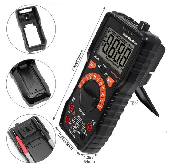
Multimeters are categorized into pointer and digital automatic types. The pointer-type multimeter employs a multifunctional measuring instrument with the head as the component, utilizing a pointer to indicate the measured value. In contrast, the digital multimeter displays the measured value directly on a liquid crystal display in numeric form, providing easy readability, and some models may include a voice prompt function.
When measuring current, the multimeter requires disconnecting the circuit under test and connecting the multimeter in series for accurate measurement. The current measurement circuit within the multimeter converts current into voltage using a shunt resistance. Careful consideration is needed when selecting the resistance value of this shunt resistor. If the resistance value is too large, it can result in a significant voltage drop, affecting the normal operation of the measurement load. Additionally, a larger resistor value leads to increased power dissipation, causing the resistor to heat up. Therefore, it is essential to avoid prolonged measurement of large currents with a multimeter.
Balancing these concerns, a smaller resistance value is generally preferable. However, the resistance should not be excessively small, as this would lead to a smaller voltage drop. In such cases, the subsequent measurement circuit must meet specific requirements, as low voltage may necessitate amplification before detection by the circuit. Consequently, multimeters are not recommended for extended measurements of high currents, as achieving accurate results for high-current measurements poses challenges for general multimeter capabilities.
Working Principle of Multimeter
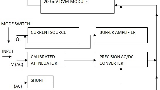
Multimeters operate on fundamental principles of electrical measurement. In DC voltage measurement, a known voltage is applied across the circuit, and the resulting current flow is measured, with voltage calculated using Ohm's Law (V = I * R). For AC voltage, the multimeter converts it to an equivalent DC voltage using rectifiers before applying the same measurement principle.
In DC measurement, the multimeter is connected in series with the circuit, measuring the voltage drop across a known resistor to calculate current using Ohm's Law (I = V / R). AC current measurement follows a similar approach, converting AC current to an equivalent DC current. Resistance measurement involves applying a known voltage across the component, measuring the resulting current, and calculating resistance using Ohm's Law (R = V / I). Modern multimeters often enhance accuracy by employing a constant current source.
Continuity testing entails sending a small current through the circuit to check for a low-resistance path. If the circuit is continuous, the multimeter signals this through an audible beep or visual indicator. Diode testing applies a small voltage to the diode, measuring the resulting current flow to determine its functionality based on observed voltage-current characteristics.
Capacitance measurement includes charging the capacitor with a known voltage and measuring the time it takes to reach a certain voltage. The multimeter then calculates capacitance based on the charging time. These varied measurement methods make multimeters versatile tools for assessing electrical properties in circuits.
Key Functions
Multimeters serve as versatile electronic instruments capable of measuring both direct current (DC) and alternating current (AC) voltages in circuits, enabling the assessment of voltage levels at different points. They are also equipped to measure DC and AC currents, facilitating the inspection of electric current flow through components or circuits. In addition, multimeters are adept at measuring the resistance of resistors and other circuit components, proving valuable for troubleshooting and confirming the integrity of electrical connections. Furthermore, these instruments perform continuity testing to ascertain whether a circuit is continuous, indicating an unbroken path for current flow and aiding in the identification of faults, such as open circuits. Multimeters can also assess the functionality of diodes within a circuit, assisting in the detection of faulty or damaged diodes. Some models are designed with the capability to measure capacitance in electronic components like capacitors.
Multimeters usually consist of a display screen, a dial or buttons to select the desired measurement function, and probes for connecting to the circuit under test. There are different types of multimeters, ranging from basic models suitable for household use to more advanced models designed for professional and industrial applications.
In summary, multimeters work by applying known electrical parameters, such as voltage or current, to the circuit under test and measuring the resulting response to determine the electrical characteristics of components within the circuit. Modern multimeters often use digital technology for more accurate and user-friendly measurements.
