How to Check the Load Cell with a Multimeter?
How can you easily determine whether a load cell is still functional? As the most essential as well as the most vulnerable part of electrical scales, load cells' proper functioning has a lot to do with the accuracy of weighing. In this article, ATO industrial automation will be showing you a simple way to test your load cell quickly and easily.
Before starting the test, make sure to have the specific load cell calibration certificate of which you're gonna pay attention to the wiring diagram with cable color codes, the output impedance and input impedance, and anything else that's necessary for your testing purposes. After each test, remember to compare the measurement values with the calibration certificate from the manufacturer to see if they closely match each other.
Measuring Output Resistance
Set up the multimeter in Ohms and measure the resistance of the input and output leads of the load cell. To be more specific, signal wires are the output and excitation wires are the input as shown in the schematic.
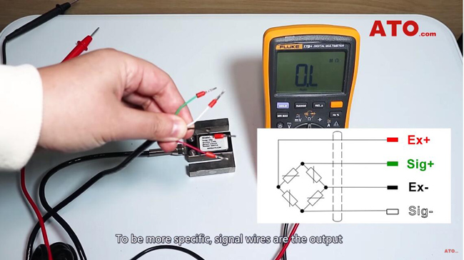
The digital multimeter is connected between the positive signal wire and the negative signal wire of the load cell. In our case, they are the green and white leads. We'll have the red probe placed on the green wire and the black probe placed on the white wire.
If the load cell is in good condition, the output between them should be equal to a value specified in the spec sheet. So the resistance should be close to 350 ohms and we get the reading of 353 ohms. That is fairly close enough. This is the test for load cell output resistance.
Measuring Input Resistance
Check the input resistance between the positive excitation wire which is red for this model and the negative excitation wire which is black. The measurement we've got should be equal to the specified value in the calibration certificate. So it should read 435 ohms or so and the meter registers 439.7 which is quite close enough. This is the test for input resistance.
Setting Up for Millivolt Signal Measurement
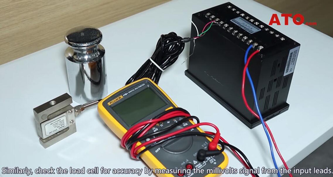
Similarly, check the load cell for accuracy by measuring the millivolts signal from the input leads. To test the load cell accuracy, you'll need a multimeter and a voltage source. In this case, we'll use a load cell controller as the external power supply to provide excitation voltage to the load cell. And this controller is driven by a 220V AC source.
Measuring Zero-Balance and Applying Load
Since the load cell is working fine we're going to supply 10VDC excitation voltage across the input leads. Plug the controller into the AC source, and now let's measure the millivolt signal across the signal wires, namely, the green and white wires and we've got the millivolt reading.
If you look at the calibration certificate, with no force applied to the load cell, the value should be zero. And we're reading zero. Apply a calibrated dead weight as specified in the calibration certificate and compare the values again. If the output voltage matches the specified value, then the load cell is good.
The above is the way to test a load cell with a multimeter. If you want to learn more about load cell testing details, please click the following video.
