What is a Strain Gauge Load Cell Construction and Working?
What is a Strain Gauge Load Cell?
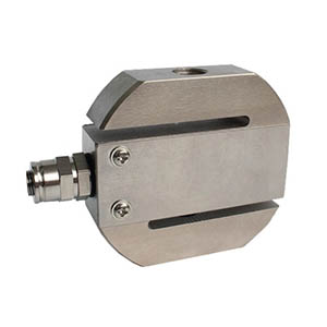
A strain gauge load cell is a conversion device used to convert a weight or pressure signal into an electrical signal. Strain gauge load cell is a kind of common type of load cell. There are different types of strain gauge lobe cell with various parameters. For example, ATO has the 5kg to 7 ton strain gauge load cell with S type design. It can withstand both tension and pressure with good output symmetry, compact structure and complete specifications. A resistance-strain load cell consists of three main components: the elastomer, the strain gauge and the measurement circuit. Resistance, inductance and capacitance are the three main types of passive components in electronics. There are some advantages of strain gauge load cell in the following.
- High impedance, low power and only very low input energy required.
- Large variation volumes can be obtained, resulting in high signal-to-noise ratios and system stability.
- Fast dynamic response, operating frequencies up to several MHz, thick b contact measurement, the object to be measured is a conductor or semiconductor.
- Simple structure. Adaptable, it can work in high and low temperatures, strong radiation and other harsh environments, more widely used.
Working Principle of Strain Gauge Load Cells
Strain gauge load cells are based on the strain effect. The strain gauges attached to the surface of the elastomer are deformed together with the elastomer by an external force. The strain gauges change their resistance and the measuring circuit converts the change in resistance into an electrical signal, thus indirectly measuring the external force. It is essentially a capacitor with variable parameters.
The strain gauge load cell is based on the principle that the elastic deformation of the elastomer (elastic element, sensitive beam) causes a deformation of the resistance strain gauges (conversion elements) attached to its surface under the action of an external force. The process of converting the external force into an electrical signal is thus completed. The internal structure of the strain gauge plays a different role in this conversion process. There are the three main components of strain gauge load cells in the followings.
Resistance Strain Gauges
A resistance strain gauge is a resistive wire mechanically distributed on a substrate made of organic material, which becomes a strain gauge. It can be divided into several types. For example, there is a kind of full bridge resistance strain gauge. Its important parameter is the sensitivity factor K. Let's introduce its significance.
A metal resistive wire of length L, with a circular cross-section of radius r, whose area is denoted S 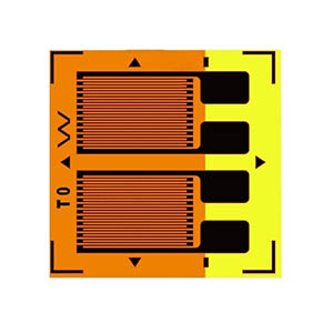 and whose resistivity is denoted ρ. The Poisson's coefficient of this material is μ. When this resistive wire is not influenced by an external force, it has a resistance of R.
R = ρL/S
When he ends are subjected to a force F, they will elongate, that is to say, deform. In addition, it can be demonstrated experimentally that the resistivity of this metal resistance wire changes after deformation, which is noted as Δρ.
It is important to note that the sensitivity factor K is a constant determined by the nature of the material from which the wire is made, and is independent of the shape and size of the strain gauge, which generally ranges from 1.7 to 3.6 for different materials.
In mechanics of materials ΔL/L is referred to as strain and is denoted as ε. It is often too large and inconvenient to use it to represent elasticity.
It is often given in parts per million as a unit and is denoted as με. So its equation is often written as this.
ΔR/R = Kε
Elastomer
An elastomer is a structural element with a special shape. Its function is twofold: firstly, it bears the external forces to which the load cell is subjected, generating a reaction to them and achieving relative static equilibrium. Secondly, it has to generate a high-quality strain field (zone) so that the resistance strain gauges pasted in this zone are more ideally suitable to the task of converting the electrical signal of the strain date.
Let's describe the stress distribution in it.
If a rectangular cantilevered beam with a hole is provided. The bottom center of the hole is subjected to pure shear stresses, but the upper and lower parts will experience tensile and compressive stresses. If a strain gauge is attached here, the upper part of the strain gauge will be subjected to tension and the resistance will increase, while the lower part of the strain gauge will be subjected to compression and the resistance will decrease. The expression for the strain at the bottom center of the hole is given below.
ε = [3Q (1+μ) / 2Eb] * [B (H2-h2) + bh2] / [B (H3-h3) + bh3]
- Q - The shear force in the section
- E - Young's modulus
- μ - Poisson's coefficient
- B, b, H, h - are the geometric dimensions of the beam
It should be noted that the stress states analyzed above are "local", whereas the strain gauges in reality should feel the "average" state.
Detection Circuit
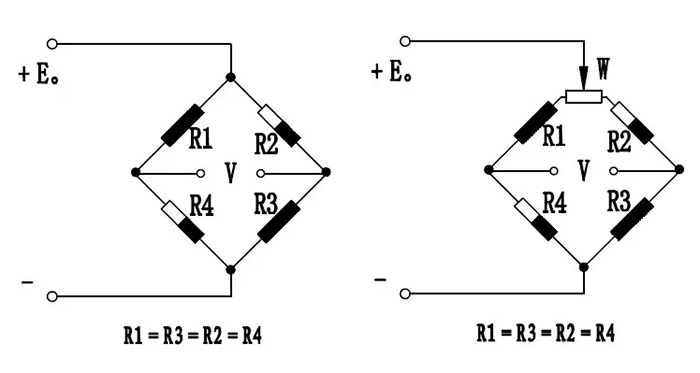
The detection circuit has the function of converting the change in resistance of the strain gauge into a voltage output. Whisten bridges are widely used in load cells because of their many advantages, such as the suppression of temperature variations and lateral force interference and the ease of solving load cell compensation problems.
Because of the highest sensitivity of the full-bridge equal-arm bridge, the parameters of each arm are the same, and the influence of various disturbances can easily cancel out each other. So the load cells all use the full-bridge equal-arm bridge.