How does PLC control Relay Module?
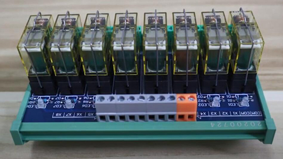
ATO relay module adopts high-current relay (1NO+1NC or 2NO+2NC), available with 2 to 32 channel, LED indicator for working status, standard DIN rail mounting. It is widely used for all MCU control, industrial automation, PLC control, smart home control. This blog shows that how does PLC control relay module.
We use a PLC and 8-channel relay module for demonstration.
Wiring & testing
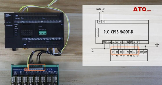
- The output terminals 00~07 of the PLC are correspondingly connected to the input terminals X1~X8 of the relay module.
- The COM terminal of the relay is connected to 24VDC+ (compatible with NPN/PNP type).
PLC program explanation
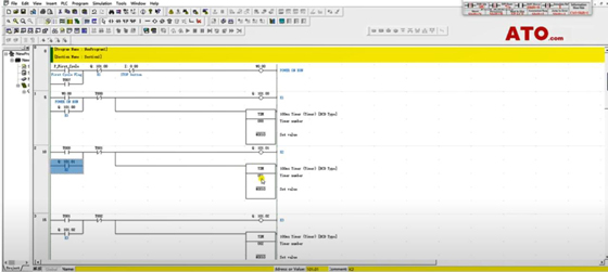
- After power on, the PLC output terminal 101.00 immediately outputs a signal, and self-locks this program.
- Timer T000 starts timing.
- T000 timing is completed, 101.01 is connected, 101.01 self-locking.
- T000 disconnects the output signal of 101.00.
- After T001 timer time is up, connect 101.02 and disconnect 101.01 output port in the same way.
- 101.00~101.07 correspond to the output signal to the relay module X1~X8.
Execute program
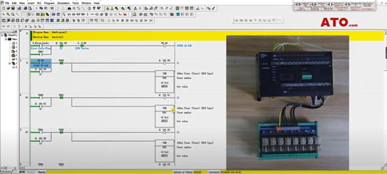
We can see that the relay module X1~X8 cyclically lights up. Compared with traditional relays, ATO relay module wiring is simpler and more beautiful. Each channel of the relay module controls a pair of normally open contacts and normally closed contacts, we can use these contacts to control more circuits.
If you want to know more about PLC control ATO relay module, view the video below.
