Relay/ Contactor Interlock Circuit Wiring
When an electrical circuit has two contactors and only one of them needs to be turned on at a time then the interlocking system is used. The interlocking system ensures that only one contactor can be on while another one will be in off condition even if we try to manually on.
Next, ATO automation will show you the circuit wiring of relay/ contactor.
The structure of relay/ contactor
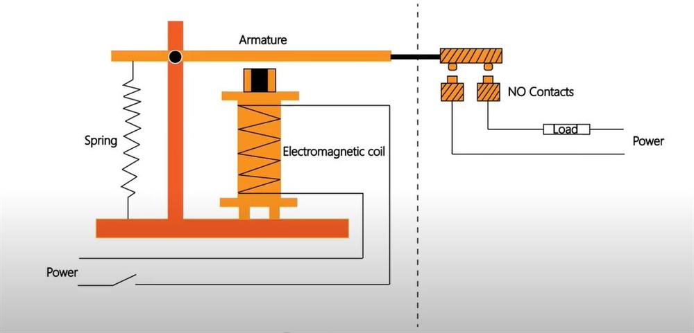
Working principle of relay/ contactor
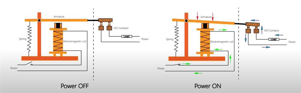
When the coil is energized, the armature is sucked down by the electromagnetic attraction, and the normally open contact is turned on (the normally dlosed contadt is disconnected).
The difference between relay and contactor
- The difference between them lies in the capacity of the contact. The contact capacity of the contactor is much larger than that of the relay.
- Relays are usually used in low-voltage control systems, and are usually controlled by control systems such as PLC, single-chip microcomputer, button switches, etc.
- Contactors are usually used on the high-voltage system side and are usually controlled by relays (low-voltage control high-voltage/ safe voltage control dangerous voltage).
Relay/ Contactor interlock circuit
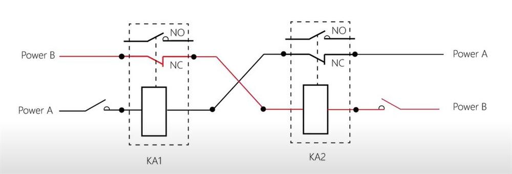
KA1 and KA2 respectively connect the circuit in series to the normally closed (NC) contact of each other.
When KA1 is powered on, the normally closed (NC) contact of KA1 is disconnected. No matter whether Button B is closed or not, KA2 cannot pass current.
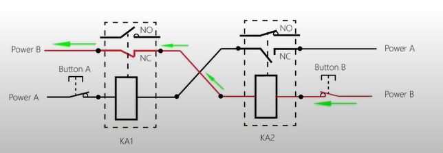
When KA2 is powered on, the normally closed (NC) contact of KA2 is disconnected. No matter whether Button A is closed or not, KA1 cannot pass current.
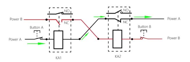
How to wire relay/ contactor interlock circuit?
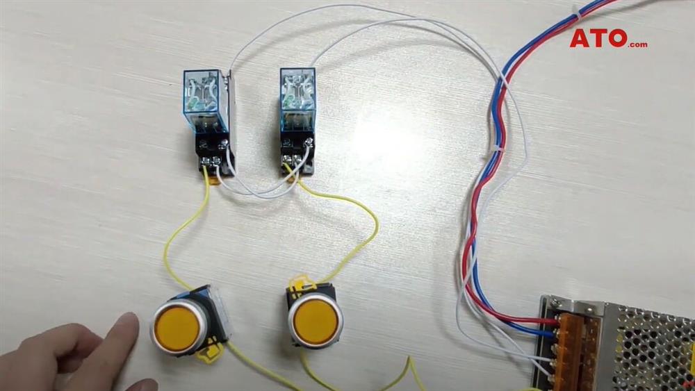
- The two relays have been connected to the interlock circuit. Their coil circuit are connected in series to each other's normally closed contacts.
- When one of the start buttons is pressed, the corresponding relay is activated.
- The other relay start button is invalid.
- After the restore button, another relay is activated, the first relay activation button is invalid.
See more details through the video below.
