How to Control the Rotation Angle of Stepper Motor?
A stepper motor, also known as step motor or stepping motor, is a brushless DC electric motor that divides a full rotation into a number of equal steps. The motor's position can be commanded to move and hold at one of these steps without any position sensor for feedback (an open-loop controller), as long as the motor is correctly sized to the application in respect to torque and speed.
Today, we will talk about how to control the rotation angle of stepper motor.
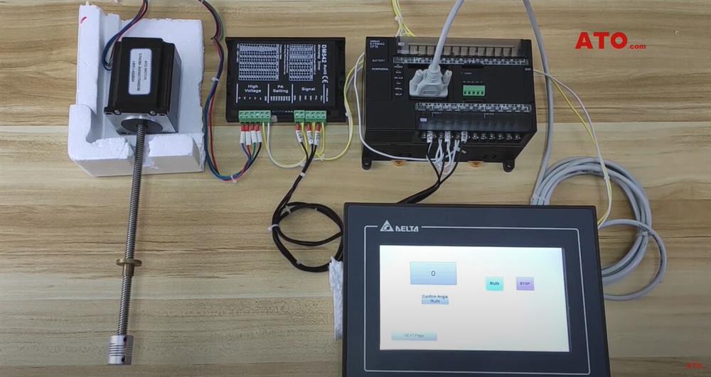
Before the operation, the materials we need are ATO stepper motor and driver, 24VDC power supply (ATO switching power supply) relay, PLC (Omron CP1E N4ODT-D), HMI (Delta DOP 107CV).
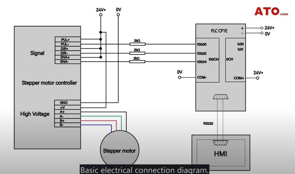
Basic electrical connection diagram
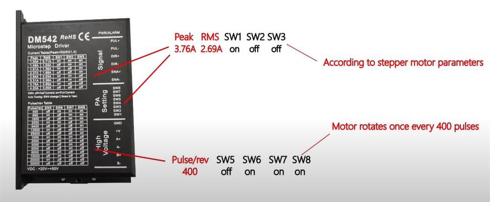
Driver setting
Control logic
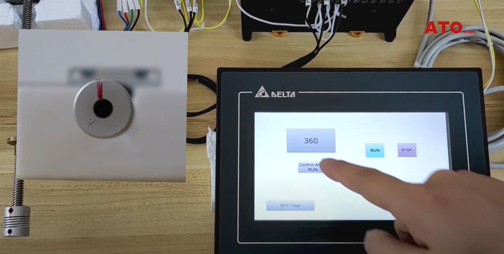
- Press RUN on the HMl, the stepper motor rotates at a constant speed.
- Press STOP on the HMl, the stepper motor stops rotating
- Enter the angle in the HMl angle input box, press the confirm key, and the stepper motor rotates to a specified angle.
Wiring
Yellow is 24V+, white is 0V. Conneting the wires according to the circuit diagram.
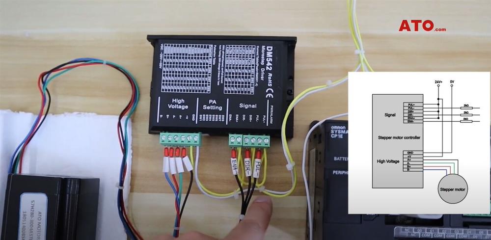
The PLC output commom terminal is connected to 0V. Note that the controller needs to connect a 2kΩ resistor to receive 24V signals.
PLC and HMI communicate with RS232, and 24VDC power supply is connected to HMI. The 4 power lines of the stepper motor are connected to the drive A+, A-, B+, B-.
PLC data storage area address allocation
- D100 Default start frequency storage area
- D200 Accelerated frequency storage area
- D201 Deceleration frequency storage area
- D202 Target frequency storage area low
- D203 Target frequency storage area high
- D204 Target pulse output number storage area low
- D205 Target pulse output number storage area high
- W0.00 RUN-W000
- W0.01 STOP-W001
- W0.02 Angle confirm-W002
PLC programming
When it is connected for the first time, reset D100 (default output frequency) to zero.
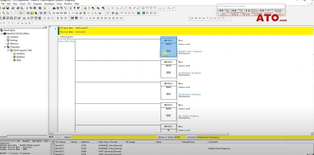
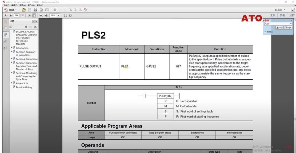
Store the pre-store data in the D200~D205 register area PLS2 instruction reference.
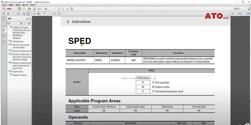
We can see the meaning of SPED instruction from Omron PLC programming manual.
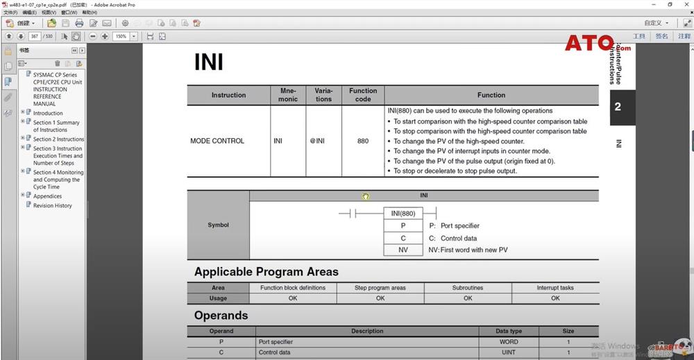
Then comes the instruction explanation of PLS2. INI is an interrupt command (used here as a stop command).
This is the rotation angle input box, corresponding to D204 (target pulse storage area) in the PLC.
The maximum input value is 360. Adjust the gain so that the data received by the PLC is 400 when the input is 360° (because the 400 pulse stepper motor ratates once).
The RUN button corresponds to W000, STOP corresponds to W001, and the input angle confirmation button corresponds to W002.
Running the stepper motor
When it is turned on, it runs directly, and the stepper motor rotates at the default speed (D100 is the default frequency output register area).
Press STOP to stop rotation. Let's try to enter a fixed rotation angle. Enter 360 and the motor will rotate 360°.
Enter 180 and the motor will rotate 180°. Input different data, the motor will rotate the corresponding angle.
Click the video below to learn more details.
