How to Set VFD Analog Output?
Variable frequency drive (VFD) is a power control device that uses frequency conversion technology and microelectronics technology to control the AC motor by changing the frequency of the motor's working power supply. The variable frequency drive is mainly composed of rectification, filtering, inverter, braking unit, driving unit, detection unit and micro-processing unit. It adjusts the voltage and frequency of the output power supply by switching on and off the internal IGBT, and provides the required power supply voltage according to the actual needs of the motor, thereby achieving the purpose of energy saving and speed regulation. In addition, the VFD has many protection functions, such as overcurrent, overvoltage and overload protection, etc. Now, we will talk about ATO VFD analog output setting and wiring.
ATO VFD analog output needs to set P4.17 and P4.18. The output type is set to frequency, and the output voltage is 0 to 10V.
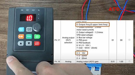
Jumper JP2 to “V” (jumper to “I” when the output is current).
The measuring instrument is connected to AO and GND.
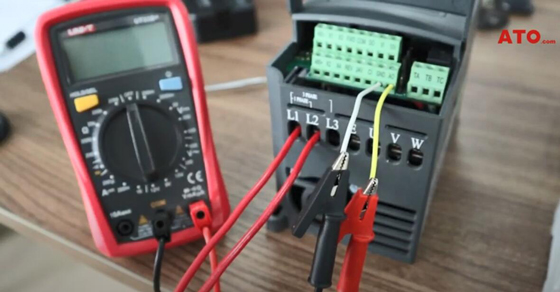
We will use a multimeter to measure the output.
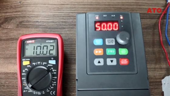
RUN VFD, observe the output voltage.
When the rated frequency is 50Hz, the voltage output is 10.45V.
So we need to set the gain (P4.18).
Decrease P4.18 gradually until the output voltage is 10.0V when the rated frequency is 50Hz.
Then the setting is completed.
You can view the video below to learn more about ATO VFD analog output setting and wiring. In addition, ATO.com online store provides single phase VFD, single to three phase VFD, 220v to 380v VFD, 120v input VFD, three phase VFD and non-enclosure VFD for your choices, power capacity from 1/2 hp to 20 hp, buy now!
