How to Wire 3-phase Induction Motor?
Thu, Apr 07 by ATO.com
3-phase induction motor is an electromechanical energy conversion device which converts 3-phase input electrical power into output mechanical power. 3-phase induction motor consists of a stator and a rotor.
Today we will show you the forward and reverse wiring of the 2hp 3-phase inducton motor. It can be realized by changing the wiring position of any two phases.
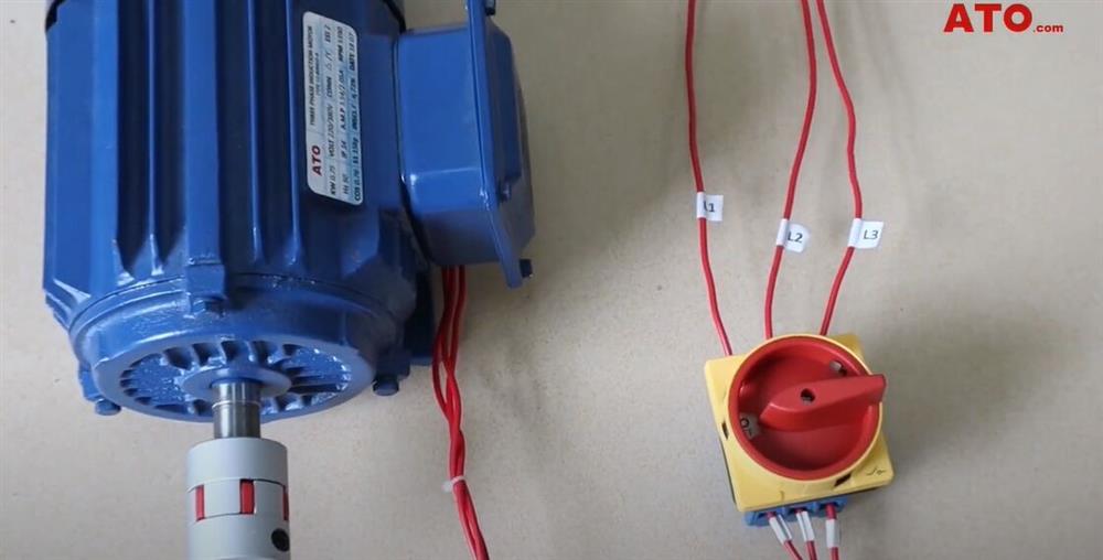
Wiring of Three Phase Induction Motor
At this time, the wiring sequence of the motor is L1, L2, L3. Start the motor, and the motor rotates counterclockwise. Swap L2 and L3, Start the motor, and the motor rotates clockwise.
3-phase induction asychronous motor forward and reverse circuit
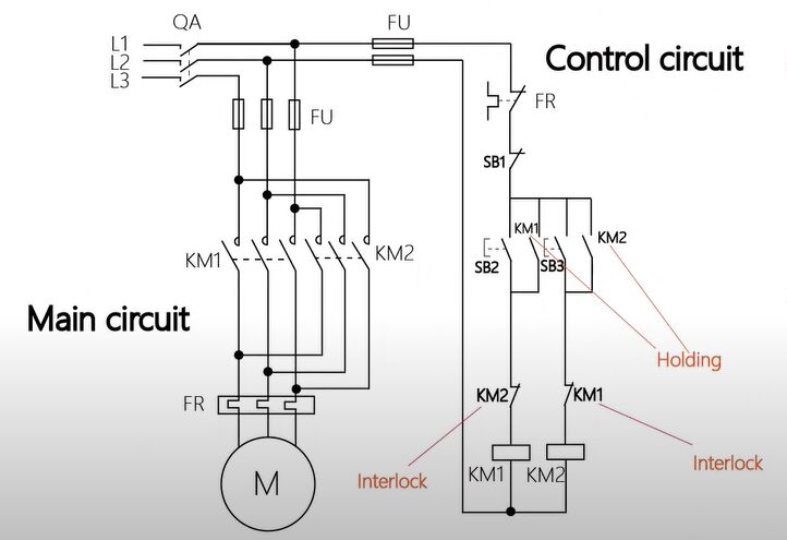
Control logic:
- Press the forward button SB2, the coil of thecontactor KM1 is energized, the normally opencontact of KM1 is closed, the normally closedcontact is disconnected (interlocked with KM2),and the motor rotates forward.
- Press the reverse button SB3, the coil of thecontactor KM2 is energized, the normally opencontact of KM2 is closed, the normally closedcontact is disconnected (interlocked with KM1),and the motor reverses.
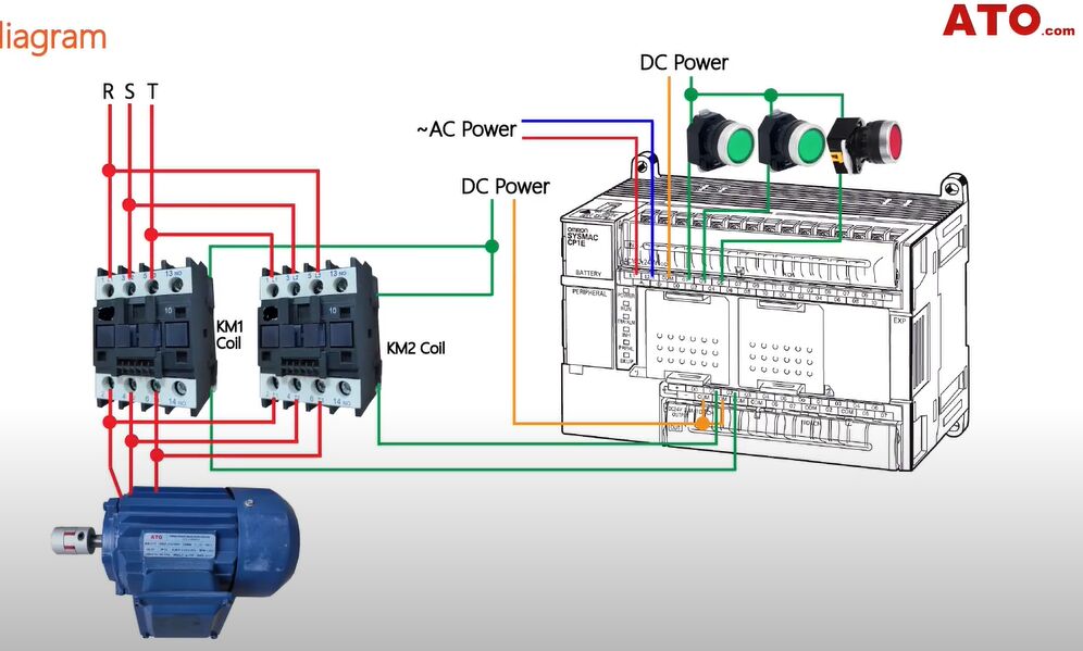
Wiring diagram of three phase motor
PLC Programing
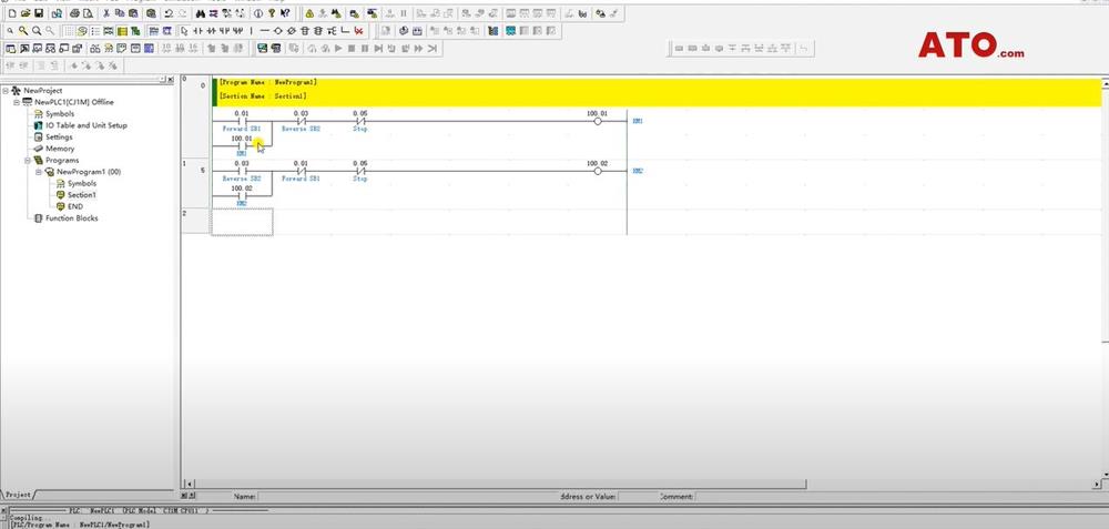
- 0.01 is the forward start signal. 100.01 (KM1) is the output signal of the forward rotation contactor.
- 0.03 is the reverse start signal.
- 100.02 (KM2) is the output signal of the reverse contactor. 100.01 self-holding forward signal.
- 0.03 forms an interlock with the forward rotation program (when performing reverse rotation, the forward rotation program is disconnected).
- 0.01 forms an interlock with the reverse program (when the forward rotation is executed, the reverse program is disconnected). 0.05 is the top signal.

- The simulation turns on 0.01, and KM1 (forward rotation) has output at this time.
- When 0.01 is turned OFF, because 100.01 is in self-holding state, KM1 output is not disturbed.
- Turn on 0.03, KM2 (reverse) has output.
- The interlock command of 0.03 takes effect, and KM1 (forward rotation) stops output.
- When the program is turned forward again, the reverse program will lose its effect.
- Turn ON the stop command 0.05, and both the forward and reverse outpout will stop.
See more details about the wiring of 3-phase motor below.
