How to Wire and Test Rotary Encoder?
The rotary encoder is a device used to measure the speed and cooperate with PWM technology to realize rapid speed regulation. The photoelectric rotary encoder can convert the angular displacement, angular velocity and other mechanical quantities of the output shaft into corresponding electrical pulses through photoelectric conversion. output (REP). Divided into single output and dual output. The technical parameters mainly include the number of pulses per revolution (dozens to thousands), and the power supply voltage. Single output means that the output of the rotary encoder is a set of pulses, while the rotary encoder with double output outputs two sets of pulses with phase A/ B difference of 90 degrees. Through these two sets of pulses, not only the speed can be measured, but also the rotation can be judged direction.
A rotary encoder is a position sensor used to determine the angular position of a rotating shaft. It can be used with an Arduino through modules to achieve such functionality. With two main types of rotary encoder available (Absolute encoder and Incremental encoder) that adopt different functional technologies, how does all of them work?
Next, we choose the model ATO-IRE-600PS of ATO high accuracy incremental rotary encoder and torque motor as examples to show you how to connect the encoder to the torque motor and makes the motor rotate.
Step 1: Wiring
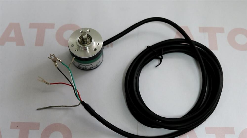
1. This NPN output, 600 ppr incremental rotary encoder equipped with 5 wires, 0V of black wire, 24V of red wire, A phase of green wire, B phase of white wire and a shield wire.
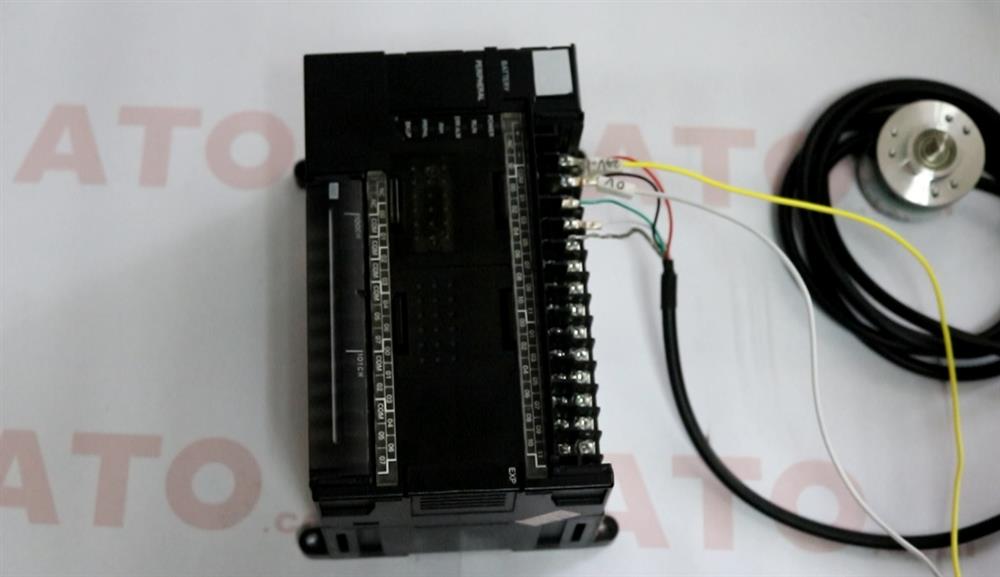
2. In order to better and more intuitively observe the pulse output of the encoder, we use a PLC with a high-speed counter function. Now connect the phase A and phase B to the PLC high-speed counter interface.
Note: The encoder is a precision device and cannot be severely impacted.
Step 2: Testing
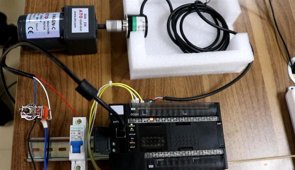
Preparation tool: a rotary encoder, a torque motor (with positive and negative rotation function), a PLC with a high-speed counter function and a coupling.
1. Connecting incremental rotary encoder to torque motor by a coupling to make encoder rotate.
2. Powered on, PLG can work normally.
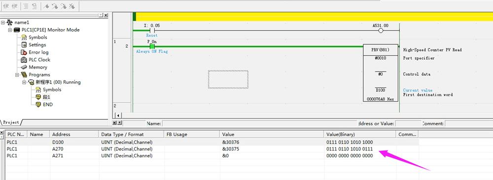
3. Press switch, the motor rotate, the changes in pulse numbers can be observed from PLC monitoring software in real time.
4. Press switch to make motor rotate reversely, the pulse number decrease gradually on PLC monitoring software.
 In addition, you can watch the video below for more detailed wiring instructions.
