How to Wire Stepper Motor?
Fri, Apr 15 by ATO.com
Stepper motor is an open-loop control motor that divides a full rotation into a number of equal steps. The motor's position can be controlled to move and hold at one of these equal steps. Stepper motors come in many different sizes and styles, and they are widely used in a variety of automated control systems.
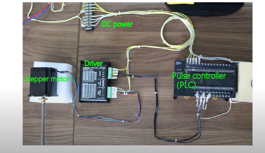
The composition of the stepper motor control system:
- Pulse controller
- Stepper motor driver
- Stepper motor (Microcontroller, PLC, etc.)
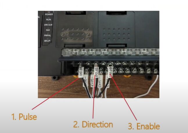
Pulse controller
Output signal voltage:
- 5V
- 12V
- 24V
Output three signal:
- Plus
- Direction
- Enable
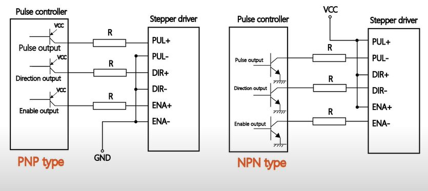
Stepper motor driver
Signal port explanation
PUL+/-, stepper pulse signal input port.
DIR+/-, stepper motor direction control port.
ENA+/-, stepper motor enable signal input port.
- When the Enable signal = ON, restart the drive andyou can freely rotate the motor by hand.
- lt can be connected directly when the input signal is 5VDC.
- When the input signal voltage is 12VDC, a 1kΩ resistor(power greater than 1/ 8W) is required in series.
- When the input signal is 24VDC, a 2kΩ resistor (power greater than 1/ 8W) is required in series.
Signal wiring
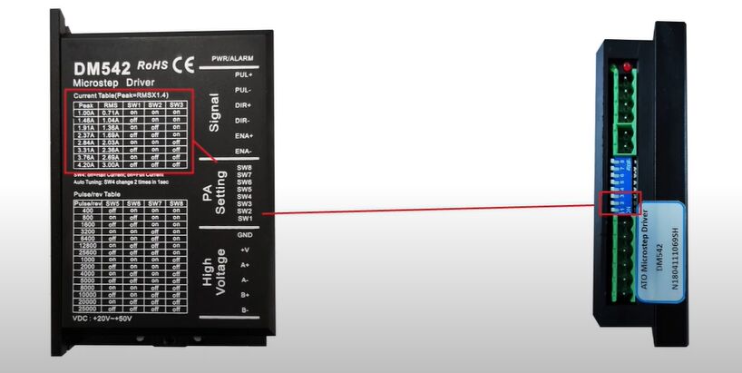
PA setting
- Drive current setting, according to the stepper motor specifications to set the DIP switch.
- DIP switch setting of the number of pluses received per revolution of the stepper motor.
High voltage
Drive power interface: +V: 20~50+, GND: 0V
Motor drive line (2-phase hybrid stepper motor): A+, A-, B+, B-
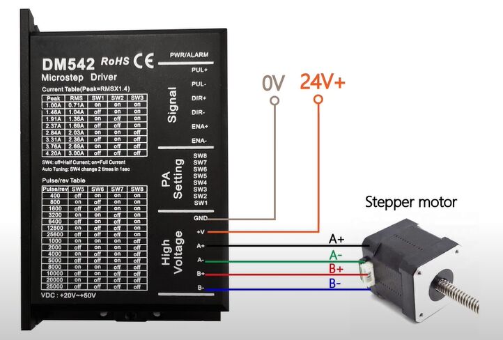
Complete wiring diagram
See more information below the video.
