
Inductive Proximity Sensor
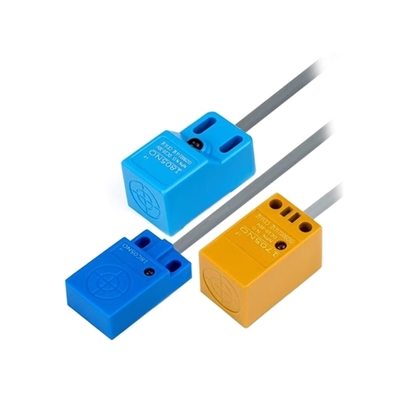
Square Inductive Proximity Sensor, Rectangular, NPN/PNP, NO/NC
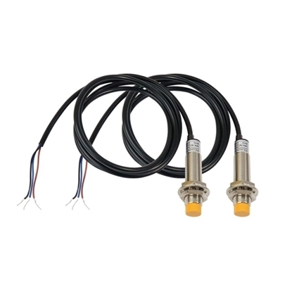
M12 Proximity Sensor, Inductive, NPN NO, Unshielded, 4mm
An inductive proximity sensor, also known as a proximity switch, is a noncontact device that employs a high-frequency oscillator to generate an alternating field. When a metal target nears, induced eddy currents attenuate the oscillation; this change is demodulated into discrete or analog outputs in PNP, NPN, or multiple wiring formats. Detection distance is governed by target conductivity and permeability, while shielded, unshielded, and varied housing styles enable adaptable industrial mounting.
How Inductive Proximity Sensors Work
Inductive proximity sensors operate based on Faraday’s Law of Electromagnetic Induction. The internal structure consists of an oscillator, a coil, a detection circuit, and an output stage.
- High-frequency field generation: The oscillator drives the coil to produce a high-frequency alternating electromagnetic field from the sensing face.
- Eddy current effect: When a metallic object enters this field, eddy currents are induced within the metal surface.
- Oscillation attenuation: The eddy currents consume energy from the oscillator, causing the oscillation amplitude to decrease or stop.
- Signal output: The detection circuit converts this change in oscillation state into a discrete (PNP/NPN) or analog output signal.
Two detection modes: Inductive sensors can operate via amplitude change (target approaching causes oscillation decay) or frequency change (different metals cause frequency shifts).
Inductive Proximity Sensor Types and Application Scenarios
| Housing Type | Thread / Size Options | Typical Sensing Distance | Key Applications |
| Cylindrical (Threaded) | M8 proximity sensor, M12, 12mm proximity sensor, M18, 30mm proximity sensor | 1 mm ~ 15 mm | General industrial automation, position detection, limit switching, conveyor systems. |
| Miniature | ∅3mm /∅4mm /M5 (Miniature type) | 0.8 mm ~ 1.0 mm | Precision mold positioning, micro-robotics, small-space assembly (ideal for miniature inductive proximity sensor applications). |
| Rectangular / Block | Flat panel mount | 5 mm ~ 8 mm | Heavy vibration environments and applications requiring a rectangular proximity sensor for flat surface mounting. |
| Ring / Doughnut | Embedded (through-hole) | Detects small passing objects | Inductive ring sensor used for detecting steel balls, springs, rivets, screws, nuts, and broken wire detection. |
Environmental Ratings (IP & Temperature):
- IP Rating: Rated IP67 proximity sensor (dust-tight and protected against temporary immersion) and IP68 (continuous immersion) options are available for washdown stations and outdoor use.
- High-Temperature Models: For extreme environments, we offer a specialized high-temperature proximity sensor and high-temperature inductive proximity sensor suitable for furnace-side operations, cold storage, and outdoor winter conditions (Standard: -25°C~+70°C; Wide-temp: -40°C~+100°C).
- Built-in Anti-Interference: Our sensor inductive proximity designs feature robust EMI resistance. Shielded (flush) versions are available to allow embedding into metal, while unshielded (non-flush) versions offer longer sensing ranges. Specific weld-immune proximity sensors are also available for welding environments.
How to Select an Inductive Proximity Sensor
When selecting a proximity switch, you must focus on four core dimensions: Target Metal Type → Sensing Distance (with margin) → Mounting Space (Thread Size) → Operating Environment (IP/Temperature/Interference).
| Dimension | Key Considerations | Recommendations |
| Target Metal Material | Ferrous metals (iron/steel) give the longest distance; non-ferrous metals (aluminum/copper) shorten it. | For aluminum/copper, choose a long-range inductive proximity sensor, or select a Factor 1 (K1) model. |
| Sensing Distance | Rated distance (Sn) is measured with standard mild steel. | Always reserve a margin: select a sensor with a rated distance at least 2x your actual need. |
| Mounting Space | Determined by the available fixing hole diameter. | Match the thread to your equipment. Tight spaces require miniature M4/M5 or ∅3/∅4 diameters. |
| Environment | Moisture = need IP67/IP68; extreme temps = need wide-temp; high EMI = need shielded/anti-EMI. | Choose IP67 for washdown. Choose high-temperature models for furnaces/cold storage. |
Target metal size requirement
- Per EN 60947-5-2, the standard target for rating inductive proximity sensors is a 1mm-thick square steel plate, with a side length equal to the larger of the sensor's sensing face diameter or three times the rated sensing distance (Sn).
- As a practical rule of thumb, the target metal object should be at least three times the diameter of the sensing face.
- Smaller targets reduce effective sensing distance significantly and may cause detection failure. For such applications, choose a smaller thread size (e.g., an 8 mm proximity sensor rather than 30 mm) or select a long-range inductive proximity sensor to compensate.
Inductive Proximity Sensors vs Capacitive Proximity Sensors
| Parameter Inductive | Proximity Sensor | Capacitive Proximity Sensor |
| Detectable Targets | Metals only | Metals, plastics, paper, liquids, powders, wood |
| Working Principle | Electromagnetic induction (Eddy current) | Changes in capacitance |
| Response Frequency | High (up to 2 kHz) | Low to medium |
| Environmental Stability | Unaffected by dust, oil, or moisture | Affected by humidity, temperature, and material buildup |
Selection Principle: If your target is metal, always prioritize the inductive type. When comparing an inductive and capacitive proximity sensor, the inductive offers faster response and superior reliability in dirty environments.
FAQs about Inductive Proximity Sensors
Q1: What is the supply voltage range for a DC inductive proximity sensor and how to connect its 3-wire cable?
A1: Most DC-powered inductive proximity sensors operate on 10-30 VDC. The 3-wire cable uses brown for +V, blue for 0V, and black for the output signal. Two-wire versions wire the load in series with the supply but have higher residual voltage and minimum load current requirements.
Q2: What are the output differences for an inductive proximity sensor when choosing NPN, PNP, or 2-wire?
A2: NPN sinks to ground, PNP sources to +V, and 2-wire is simpler but less flexible. When an inductive proximity sensor appears to trigger early, this is usually not false triggering but a reduced effective distance caused by the target material: ferrous metals give 100% of rated range, while aluminum and copper attenuate to only 30-35%. Always select a sensor with extra margin to compensate.
Q3: What is the correct installation sequence for an inductive proximity sensor?
A3: Start by selecting shielded (flush) for embedding in metal or unshielded (non-flush) for longer range. Secure fixing nuts without over-tightening to avoid housing damage. Connect wires correctly: brown to +V, blue to 0V, and black to signal for 3-wire types. Complete the setup by testing the inductive proximity sensor with its built-in LED to verify output switching at the intended distance.
Q4: Why does an inductive proximity sensor behave erratically near motors or drives?
A4: Erratic operation near variable-frequency drives and contactors is caused by electromagnetic interference (EMI). Solutions for your inductive proximity sensor include choosing EMI-hardened models with built?in surge protection, using shielded cable, routing sensor wires separately from power cables, maintaining physical distance from noise sources, and performing on-site testing under full load to confirm stability.
