How to Select and Debug SCR Power Controller?
The thyristor power controller adopts thyristor (SCR or TRIAC) as the switching component, namely, a non-contact switch that can quickly and accurately control the closing time. It serves as an essential terminal equipment for power control designed for high precision and high dynamic indicators. It is worth noting that different loads and constraints of the operation environment determine different control modes and require various supporting equipment. Among control modes there are phase angle control, distributed crossover and time proportional zero crossover. In actual use, SCR power controllers can be sorted into single-phase SCR power controllers and three-phase SCR power controllers in accordance with their load types, power supply types and power supply voltage levels. So, how should we choose the right type of power controller and bring its optimum performance into play with minimal damage? The following passages will give you the answer.
In the three-phase 380V power supply grid, the "SCR power controllers" compatible with single-phase 220V and single-phase 380V power sources are called "single-phase SCR power controllers." Generally, single-phase SCR power controllers are recommended in the following two situations:
- The single-phase type is a suitable choice when the load power is small because it will not cause serious imbalance to the grid. When using a single-phase controller, you are advised to consider the capacity of the circuit breakers and cables of the power supply circuit. In order to reduce the controller’s impact on the power grid, use 380V as much as possible.
- If the total load power is very large but can be decomposed into multiple groups of single-phase loads, it is highly suggested to choose multiple single-phase SCR power controllers. When in use, the SCR power controllers and loads of each group should be allocated to the three-phase power source as evenly as possible. This not only keeps the balance of the three-phase, but also reduces the workload of electric equipment, which is very conducive to the manufacture, installation, debugging and maintenance of equipment.
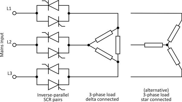
SCR power controller compatible with the three-phase 380V power supply is called the "three-phase SCR power controller". There are generally two connection methods for loads: Delta connection and star connection. When the equipment works with a three-phase load, a three-phase SCR power controller is proper for use. This solution is easily put into practice However, high-power three-phase SCR power controllers need to use copper bars or cables with large cross-sectional area, and require good heat dissipation conditions.
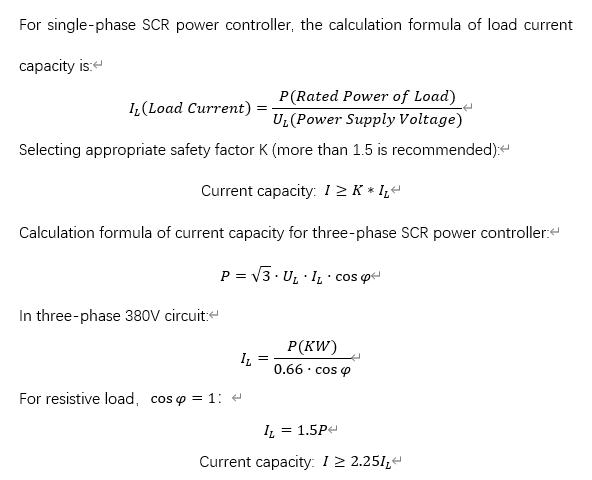
After illustrating the application conditions of single-phase and three-phase controllers, let’s move on to the part of current capacity selection.
When choosing the SCR power controller, purchasers should first determine the type of load and its corresponding rated power.
As the product is delivered to you, make sure to take a thorough examination of the device before use. You can’t be too careful to deal with anything related to electricity. Here are some steps for debugging that may be of help for you.
Check the manipulator
- Check whether the manipulator suffers damage by reason of improper transportation.
- Open up the control panel, check whether the wires are loose or fall off due to transportation, and tighten all the wiring terminal screws with a screwdriver.
- Open up the control panel, check whether the screws connecting the copper bar and the SCR module are loose; if so, then tighten the screws.
Examine the transformer
Take a simple examination of the transformer before applying the transformer primary side for voltage regulation. Disconnect the primary side and the secondary side of the transformer and measure primary-side-to-secondary-side resistance, primary-side-to-the-ground resistance and secondary-side-to-the- ground. Make sure that all these values shall not be less than 1MΩ. Check whether the clamping screw of the transformer is loose, whether the silicon steel sheet loosens, if so, tighten the bolts.
Check the load
Cut off the load power supply in the furnace, and use a multimeter to measure whether the resistance of the heating wire to the ground meets the requirements. If two short circuits to the ground were found, it would cause imbalance of the three-phase current and voltage, triggering the over-current alarm, or even worse, it would cause damage to the controller. Check whether the heating wire in the furnace is disconnected or loose. After ensuring that the resistance of the heating wire to the ground meets the requirements, you can attach the wire to the secondary side of the transformer, and tighten the bolts. If the bolts are loose, it may cause poor contact and damage the controller.
Light load experiment
Connect the input power cord of the controller, disconnect the controller and the load, and use three 60W/220V bulbs to simulate the load. Adopt the star connection method to connect the three bulbs to output ports of the controller. Switch on the power and do the following checks:
Check whether the neon lamp (indicator of the right phase sequence) on the control panel is on (for three-phase controller) and whether the fan is working normally. If the lamp and the fan doesn’t work, please examine the device according to the following steps:
- Check whether the controller's input voltage R-S-T voltage is normal. If it is normal, check whether the three-phase sequence gets wrong, and switch the two power cords until the neon light is on.
- At the input power port of the main circuit, there is one power cord (single-phase) or three power cords (three-phase) connecting to the power supply, and see if the wiring is off. Check whether the power transformer on the control board is damaged. If the primary or secondary side of the power transformer is open or short-circuited, remember to shut down the power first, and then you can check whether the resistance values of the primary and secondary coils are normal. If normal, the primary side is around 700 Ohms, and the secondary side is 5-10 Ohms.
If the fan is not working properly, please check whether the fan power is connected correctly. You can open up the main body of the device to see if the connection is loose. There are four LED lights on the shell, which respectively indicate different working condition of the controller.
