Stepper Motor Driver Circuit
Unipolar and bipolar driver architectures are most commonly used for stepper motors.
Unipolar stepper motor indicates the stepper motor with 2 coils and 5 or 6 lines. That is, one tap is increased in the middle of one coil. 5 lines can be seen as 6 ones. The two intermediate line of two coils can be connected. For there is tap in the middle of one coil, the current can flow towards different direction along the half way in one coil, but half of the motor coil is just used.
The unipolar drive circuit uses four transistors to drive two phase of the stepper motor. The motor configuration, as shown in Figure 1, consists of two sets of coils with center tap, and the entire motor has a total of six lines connected to the outside. Although the six-wire stepper motor is also known as unipolar stepper motor, it can actually use unipolar or bipolar drive circuit at the same time.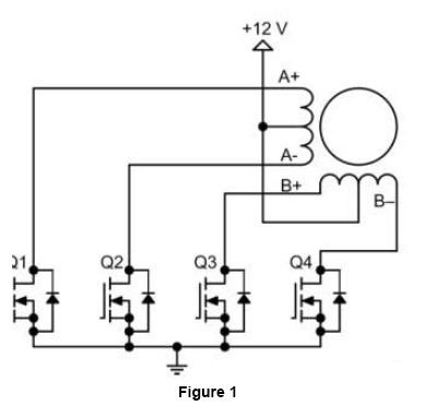 Bipolar stepper motor indicates the stepper motor with 2 coils and 4 lines. The current can flow in forward and reverse direction in two coils, so called bipolarity.
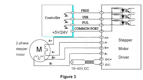
The drive circuit of a bipolar stepper motor is shown in Figure 2, which uses eight transistors to drive two phases. Bipolar drive circuit can also drive a four-wire or six-wire stepper motor. Although it can only use bipolar drive circuit, a four-wire motor can significantly reduce the cost of mass-production applications. The number of transistors used in drive circuits of bipolar stepper motors is twice that of transistors used in a unipolar drive circuit, in which four lower transistors are usually driven directly by a microcontroller while the upper transistor requires an upper driver circuit of higher cost. Transistors used in bipolar drive circuits only need to withstand motor voltage. Therefore, they do not need to clamp the same circuit as unipolar drive circuits do.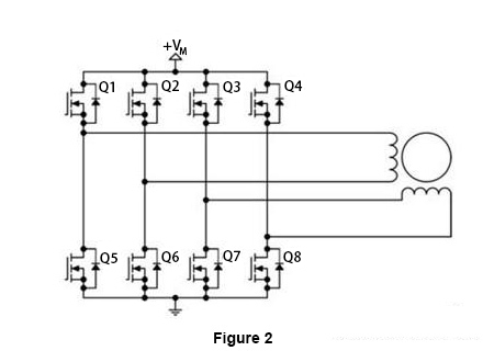 Bipolar motor features high application efficiency for the current flows in the forward and reverse directions of one coil. As for the unipolar stepper motor, the efficiency is low for half of coil is just used with most of the time. However, in terms of strict cost requirement, the unipolar motor is widely applied. But ATO.com provides all kinds of bipolar stepper motors with low cost for your reference.
Now, to learn more about the stepper motor drive circuit, we will take our stepper motor ATO47-1684A and stepper driver ATODSP42 as example. ATO47-1684A is 2-phase 4-wire bipolar stepper motor with 1.8 degree step angle. ATODSP42 is a closed-loop digital 2-phase stepper motor driver which adopts the latest 32-bit DSP control technology, suitable for Nema 11, 14, 17 stepper motors. As the Figure 3 shows, it is easily found that how to connect the stepper motor with stepper motor driver.