Test of 16 Input 16 Output Programmable Timer Relay
A PLC takes in inputs, whether from automated data capture points or from human input points such as switches or buttons. Based on its programming, the PLC then decides whether or not to change the output. A PLC's outputs can control a huge variety of equipment, including motors, solenoid valves, lights, switchgear, safety shut-offs and many others.
The physical location of PLCs can vary widely from one system to another. Usually, however, PLCs are located in the general vicinity of the systems they operate, and they're typically protected by a surface mount electrical box. In this article, we will introduce test of 16 input 16 output programmable timer relay.
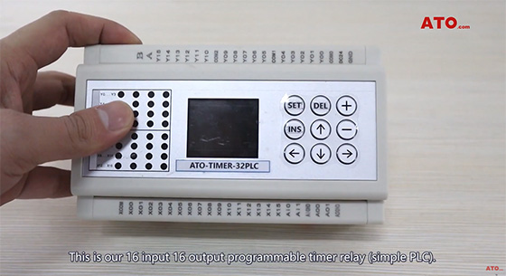
This is our 16 input 16 output programmable timer relay (simple PLC). Its control voltage is 24V DC, relay output type. Let's do a simple commissioning.
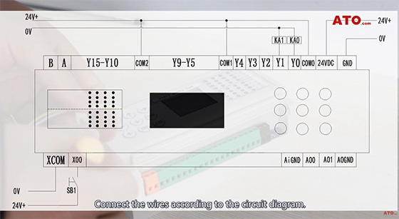
Connect the wires according to the circuit diagram. This is the output section and the power supply section. Two relays are connected at Y0 and Y1. This is the input switch SB1, connected to the input. Long press "SET" to enter the setting interface. Press "SET" again to confirm the setting. Press the up and down keys to move the selection. Press + or - to change the value. Back to the main interface, press "→" to view the status of the instruction. Press + or - to view the program.
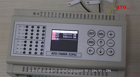
In this 00 program, I preset a program Y0=ON, Y1=ON. Press SET to enter the program editing. Change the status to run and confirm. The program starts running. Y0 and Y1 have outputs. We insert a conditional instruction to start the program when X00 is turned on. Press "INS" at the first instruction to insert an instruction. Press + or - to call trigger X. You can see that the instruction serial number is X00. When X00=ON, the subsequent program is triggered. Press "SET" to confirm.
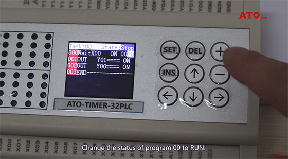
Change the status of program 00 to run. The program enters the running state and waits for X00 to trigger. When X00=ON, the program runs backward. Y0 and Y1 have outputs, and KA0 and KA1 relay coils are closed. Change the program status to "STOP" and stop running. The next video will introduce timer function, counter function, scan function and so on.
If you want to learn more about phase converter, please click this video or contact us.
